Differential amplifiers with enhanced gain and dynamic range

a technology of amplifiers and amplifiers, applied in the field ofdifferential amplifiers, can solve the problems of increasing difficulty in maintaining the quality of these amplifier parameters

Active Publication Date: 2007-08-07
ANALOG DEVICES INC
View PDF10 Cites 35 Cited by
  • Summary
  • Abstract
  • Description
  • Claims
  • Application Information

AI Technical Summary

Problems solved by technology

Maintaining the quality of these amplifier parameters has become increasingly difficult as modern integrated circuits have had to operate with increasingly-smaller supply voltages.

Method used


Image

  • Differential amplifiers with enhanced gain and dynamic range
  • Differential amplifiers with enhanced gain and dynamic range
  • Differential amplifiers with enhanced gain and dynamic range

Examples


Embodiment Construction

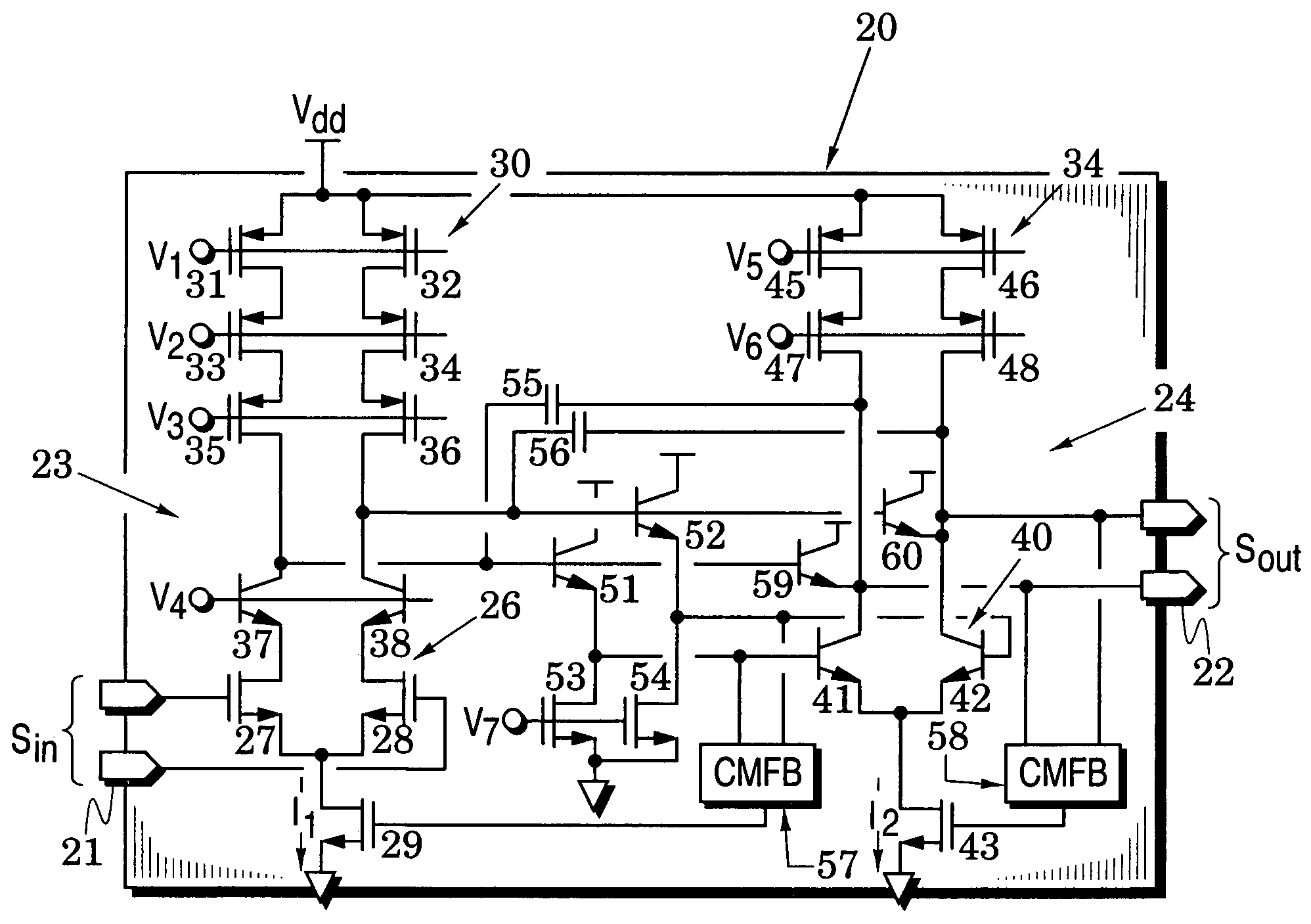
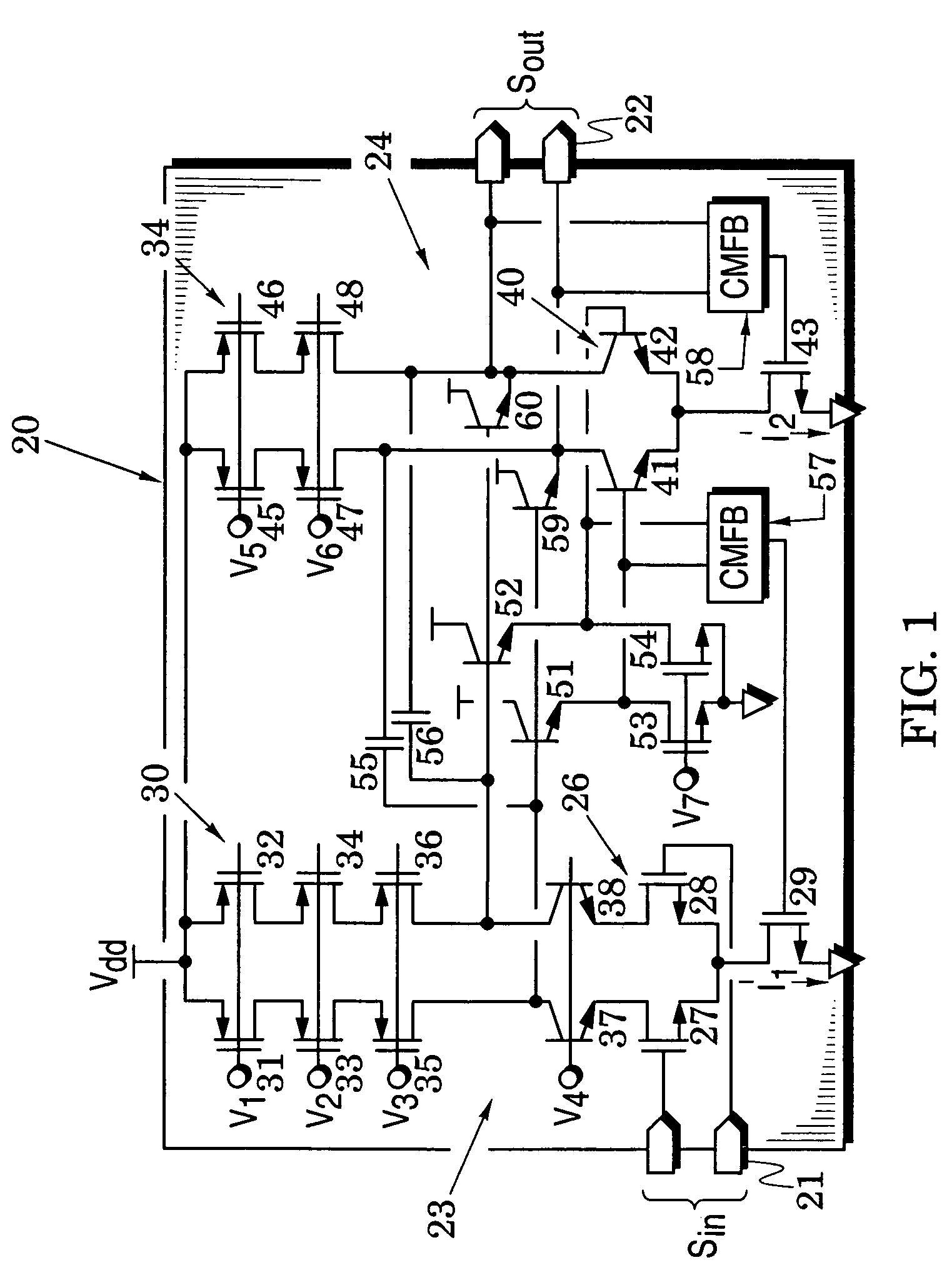
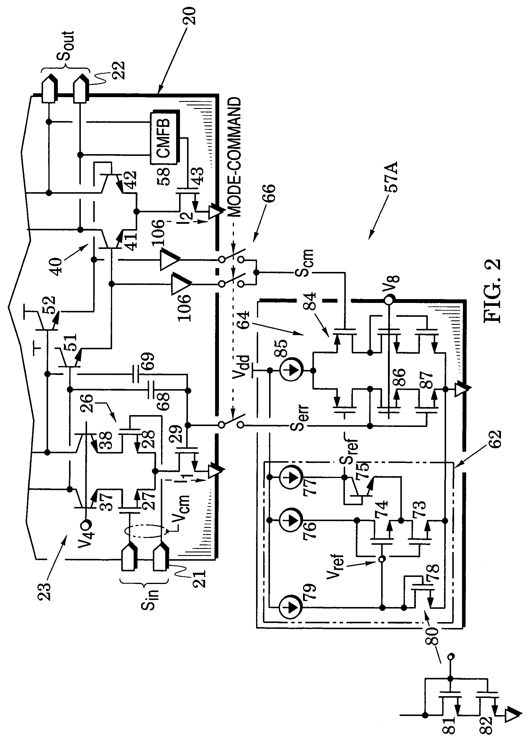
[0010]FIGS. 1-6 illustrate differential amplifier embodiments that provide enhanced gain and dynamic range. These amplifier embodiments are especially useful in applications where reduced supply voltages tends to limit signal swing and in switched-capacitor applications that require alternating operational modes.

[0011]In particular, FIG. 1 illustrates a differential amplifier 20 that processes signals from an amplifier input port 21 to an amplifier output port 22. It includes a first amplifier stage 23 that is arranged to receive differential analog signals Sin from the input port 21 and a second amplifier stage 24 that is arranged to receive signals from the first amplifier stage and provide signals to the output port 22.

[0012]The first amplifier stage 23 is formed with a first differential pair 26 of transistors 27 and 28 that receives a first tail current I1 from a first current-source transistor 29. An active differential load for this stage is formed with a pair of current-sour...


PUM


Abstract

Differential amplifier embodiments are provided for amplifying input signals with enhanced gain and dynamic range. They include first and second amplifier stages and at least one common-mode feedback circuit that is arranged to mirror and adjust a tail current to control the common-mode level of a respective one of the stages. The stages are configured with cascode elements to obtain high impedances that enhance their signal gain and the common-mode feedback circuit is configured to controllably lower the output voltage of a current source that provides the tail current to thereby enhance the amplifier's dynamic range. The amplifier embodiments are particularly suited for use in applications where they must operate with reduced supply voltages and operate in alternating operational modes.

Description

BACKGROUND OF THE INVENTION[0001]1. Field of the Invention[0002]The present invention relates generally to differential amplifiers.[0003]2. Description of the Related Art[0004]Differential amplifiers are used in a variety of signal conditioning systems (e.g., pipelined signal converters) to generate residue signals for conversion in successive converter stages to thereby provide digital codes that correspond to analog input signals. The accuracy of the residue signals and, hence, that of the signal conversion, is closely linked to operational parameters (e.g., gain and dynamic range) of the differential amplifiers. Maintaining the quality of these amplifier parameters has become increasingly difficult as modern integrated circuits have had to operate with increasingly-smaller supply voltages. Substantial benefit would thus be provided by amplifier structures that enhance these parameters in an environment of reduced supply voltages.BRIEF SUMMARY OF THE INVENTION[0005]The present inv...

Claims


Application Information

Patent Timeline
Patent Type & Authority Patents(United States)
IPC IPC(8): H03F3/45
CPCH03F3/45188H03F3/45192H03F3/45286H03F3/45291H03F3/4565H03F3/45798H03F2200/513H03F2203/45288H03F2203/45301H03F2203/45311H03F2203/45652H03F2203/45722
Inventor ALI, AHMED MOHAMED ABDELATTY
Owner ANALOG DEVICES INC
Why Eureka
Try Eureka