Hydro-electric power generating system

a technology of hydro-electric power generation and power generation system, which is applied in the direction of water-power plant, electric generator control, machines/engines, etc., can solve the problems of limited system, enhanced water flow, and inability to enhance flow or pressure properties of fluid streams, so as to achieve the effect of maximizing the inherent pressure of water flow

Inactive Publication Date: 2007-08-28
SRYBNIK SIMON +1
View PDF31 Cites 21 Cited by
  • Summary
  • Abstract
  • Description
  • Claims
  • Application Information

AI Technical Summary

Benefits of technology

[0015]It is therefore an object of the invention to provide a hydroelectric power generating system for use in flowing water bodies that maximizes the inherent pressure of the water flow by constriction of the water mass at the proximal end of a canal or spillway with respect to the normal water flow characteristics.

Problems solved by technology

This system is limited by the use of a single type of wheel and no discussion of water flow enhancement techniques is disclosed.
The spillway here only serves to direct the flow of the water to the wheel arrangement and does not enhance the flow or pressure properties of the fluid stream.

Method used


Image

  • Hydro-electric power generating system
  • Hydro-electric power generating system
  • Hydro-electric power generating system

Examples


Embodiment Construction

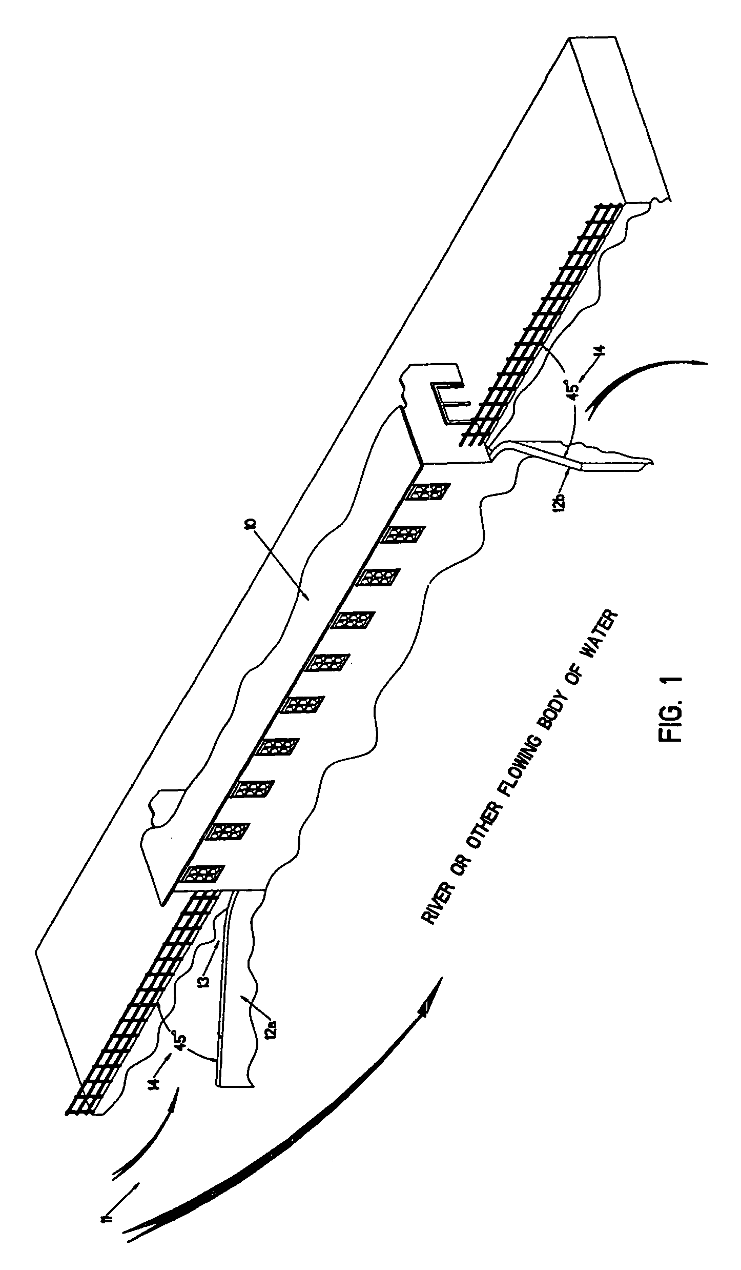
[0033]The preferred embodiments of the instant invention are described in terms of the FIGS. 1-11. Identical elements contained in various figures are designated with the same numeral in each figure.

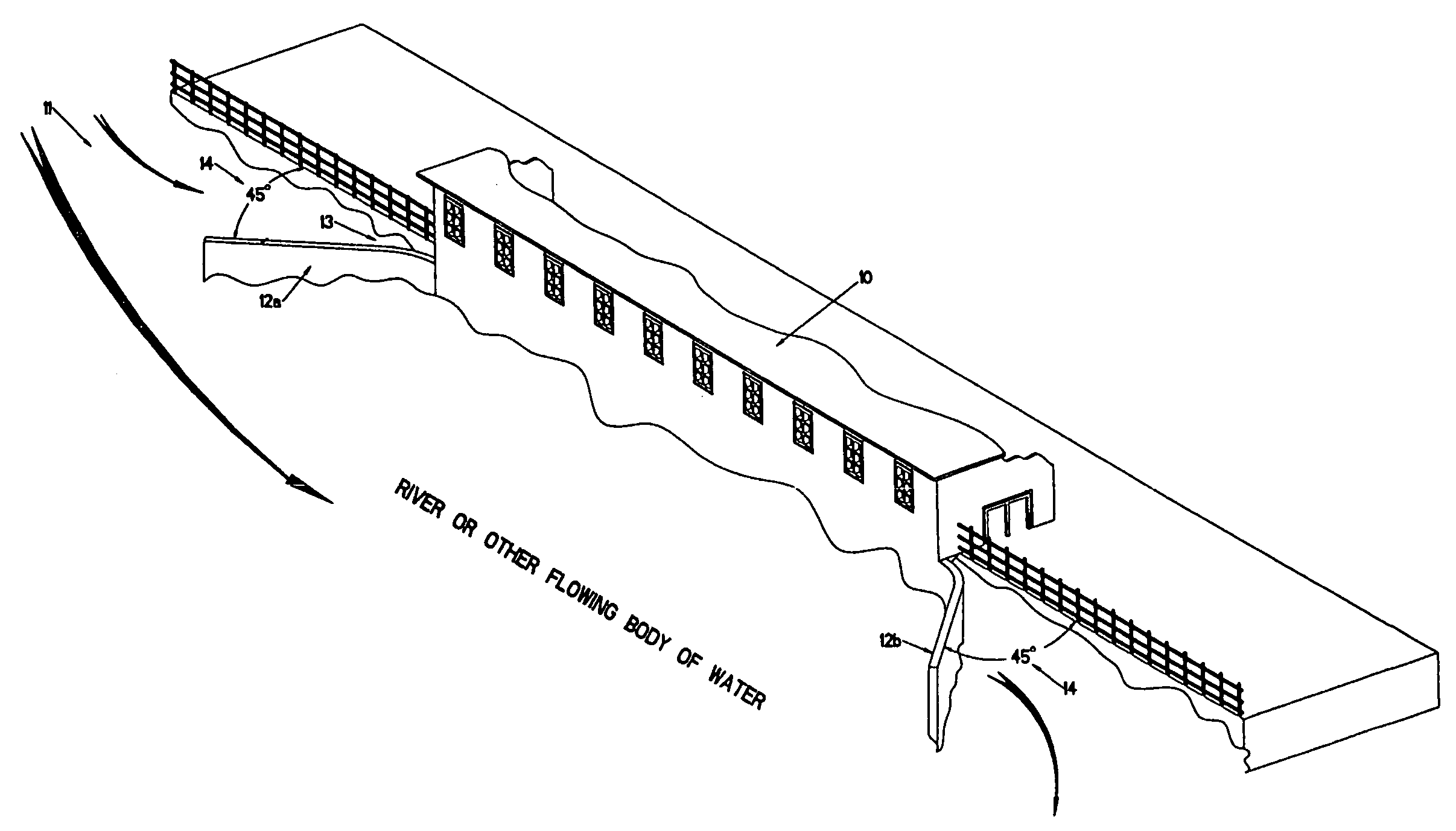
[0034]Referring now to FIG. 1, the overall design of hydroelectric power plant 10 of the instant invention is shown with respect to a flowing body of water 11. This plant may be in a fixed relationship to a bank feature if the body of water is a river or may be located on a flotation device anchored or otherwise affixed in a medial portion of the body of water. In addition, the power plant 10 may be located on the seashore or moored onto a feature such as a lighthouse, oil rig or other platform in the ocean environment. The specifics of such mooring are not included and would be standard as known to one of ordinary skill in the art.

[0035]As shown in FIG. 1, two walls or extensions 12a and 12b are located at a 45° angle (denoted as 14) with respect to the longitudinal axis of the power pl...


PUM


Abstract

A hydroelectric power plant for use in flowing bodies of water is described which includes a new spillway canal constructed to enhance the flow of water by increasing the water pressure. Because the canal has the angled feature on both ends, the water flow can be enhanced when backflow conditions exist as well as when primary flow conditions are present. In addition the canal utilizes a unique combination of both traditional and Pelton type water wheels to convert the water pressure to electric power. The canal, the extensions and both types of water wheels are also adjustable in nature to maximize the amount of power obtainable from any given body of water.

Description

BACKGROUND OF THE INVENTION[0001]The present invention relates to a hydroelectric power plant system for maximizing the use of water currents incident upon a set or series of sets of wheels connected to an electric current generating system. In addition, the invention also includes a novel water diversion system for additional maximization of the pressure of water generated by a flowing body.[0002]With the increased costs of electrical power generation from fossil fuels and the desire to generate energy without increasing pollution, it has become more important to find ways to generate electricity that use existing natural resources. This enhances the ability to add power sources in an economical fashion and to permit new avenues of supply to an increasing population without further burdening the environment. One source of interest is the use of tidal or coastal waterways and, secondarily, in marginally flowing streams.[0003]This invention, therefore, addresses the ability to harnes...

Claims


Application Information

Patent Timeline
Patent Type & Authority Patents(United States)
IPC IPC(8): F03B13/08
CPCE02B9/04F03B17/06F05B2240/241Y02E10/22Y02E10/28Y02E10/20Y02E10/30
Inventor SRYBNIK, SIMONSRYBNIK, LOUIS
Owner SRYBNIK SIMON
Why Eureka
Try Eureka