Magnetic vertical axis wind turbine

a vertical axis wind turbine and magnetic technology, applied in the field of wind turbines, can solve the problems of increasing efficiency and little spinning resistance, and achieve the effect of reducing friction within the system and maximizing the operation of the system

Inactive Publication Date: 2007-12-04
NIAGARA CENT RES
View PDF3 Cites 63 Cited by
  • Summary
  • Abstract
  • Description
  • Claims
  • Application Information

AI Technical Summary

Benefits of technology

[0013]These and other benefits are found in the present invention which provides a lift and drag-based vertical axis wind turbine in which the vertical axis and foils mounted thereon are magnetically levitated above the turbine's base, thereby reducing friction within the system. The foils are shaped to maximize operation of the system, regardless of the wind direction. More specifically, the foils are three-dimensionally shaped about the vertical axis so as to resemble the billowed sail of a sailing ship; hereinafter the foils will be referred to as sails or vanes. The sails (or vanes) capture wind through a full 360 degrees of rotation under any wind condition. The system is further provided with an axial flux alternator using variable resistance coils which can be individually and selectively turned on or off depending on wind conditions and required electrical draw requirements. The coils can also be used to produce mechanical drag on the system if required to brake the turbine in high wind conditions or for maintenance. The system may be programmed to assess whether electricity generated by the system can be or should be transmitted to a public grid or stored locally on a chargeable battery system. Finally, the system may be programmed to report system usage such as the amount of electricity produced, the amount of electricity used and the amount of electricity sent to a grid or stored. Likewise, the system can report outages to individuals and local authorities.
[0014]The system thus described is small, light in weight, and easy to install upon a flat or peaked rooftop. This vertical axis wind turbine is robust as to interaction with the weather. Most importantly, the present invention is capable of effectively using wind blowing from all sides simultaneously, including from above. Since the present invention is able to utilize wind from all directions, it can generate electricity even in low-speed winds. Also, since the wind turbine is magnetically leviated, the present invention is quiet in operation and, because the rotational bearings do not support the weight of the turbine sails, the bearings very seldom need replacement. The magnetic levitation results in very little spinning resistance, and hence, increased efficiencies. Efficiencies are also enhanced by the curved shape of the vanes or sails.

Problems solved by technology

The magnetic levitation results in very little spinning resistance, and hence, increased efficiencies.

Method used


Image

  • Magnetic vertical axis wind turbine
  • Magnetic vertical axis wind turbine
  • Magnetic vertical axis wind turbine

Examples


Embodiment Construction

[0028]In the detailed description of the invention, like numerals are employed to designate like parts throughout. Various items of equipment may be omitted to simplify the description. However, those skilled in the art will realize that such conventional equipment can be employed as desired.

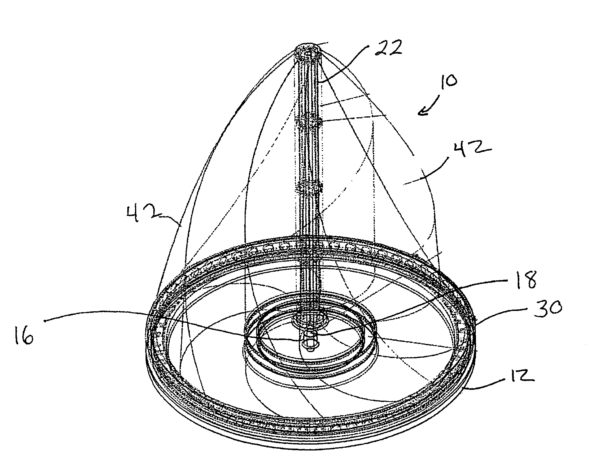
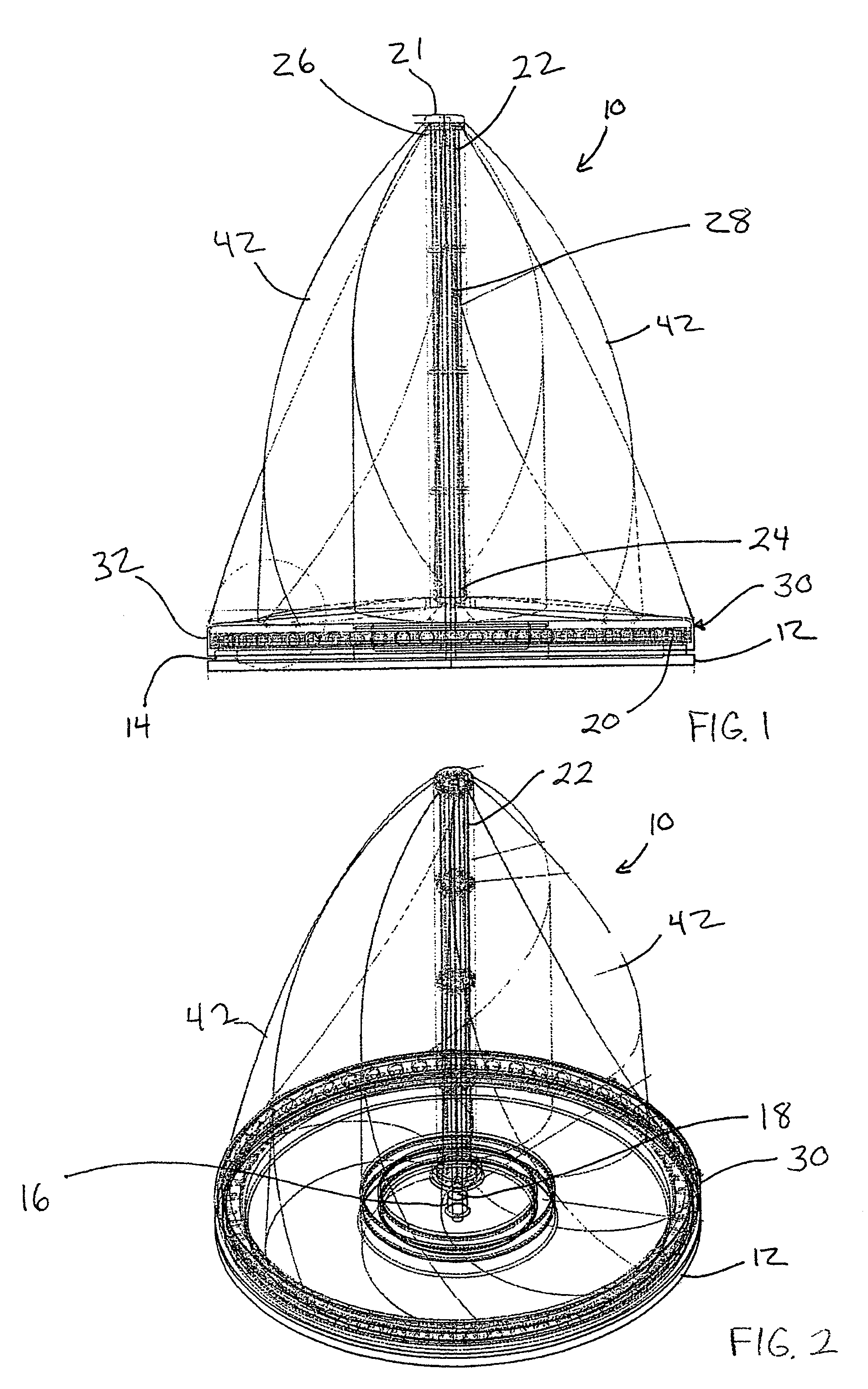
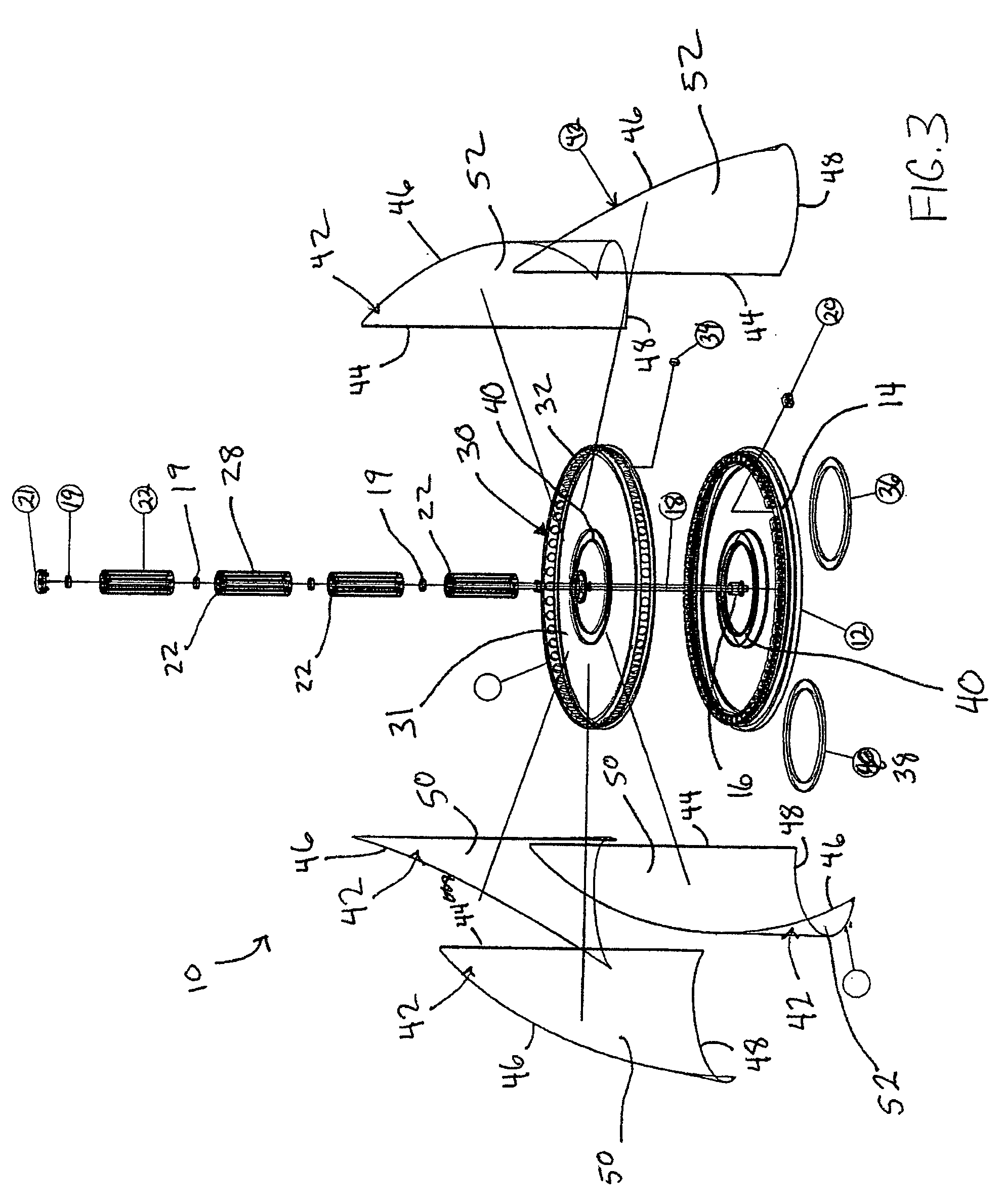
[0029]With reference to FIGS. 1 and 2, the magnetic vertical axis wind turbine 10 of the present invention is illustrated. Specifically, there is shown a substantially circular base 12 defined by a vertical edge 14 at its outer perimeter and a central hub 16. A center rod 18 attaches to central hub 16 and extends axially from base 12. Disposed around outer perimeter of base 12 on vertical edge 14 is a plurality of magnetic transformers 20. An axial shaft 22 having a first end 24, a second end 26 and axial grooves 28 along its length is pivotally mounted on center rod 18. Shaft 22 rotates axially relative to rod 18 and base 12. Center bearings 19 may be positioned on rod 18 or within shaft 22 to ...


PUM


Abstract

A lift and drag-based vertical axis wind turbine in which the vertical axis and foils mounted thereon are magnetically levitated above the turbine's base, thereby reducing friction within the system. The foils or vanes are three-dimensionally shaped about the vertical axis so as to resemble the billowed sail of a sailing ship and capture wind through 360 degrees of rotation under any wind condition. The system has an axial flux alternator using variable resistance coils which can be individually and selectively turned on or off depending on wind conditions and electrical draw requirements. The coils can also be used to produce mechanical drag on the system as desired to brake the turbine in high wind conditions or for maintenance. The system may be programmed to assess whether electricity generated by the system can be or should be transmitted to a public grid or stored locally on a chargeable battery system.

Description

BACKGROUND OF INVENTION[0001]The present invention relates generally to wind turbines, and more particular to low resistance, vertical axis wind turbines that utilize a unique airfoil design to enhance rotation in winds from a single direction, multiple directions including winds blowing from directly above, and cyclonic winds.[0002]In recent years there has been a dramatic increase in the demand for energy in all forms including fuels and electricity for heating, lighting, transportation and manufacturing processes due to the world's population rapidly increasing, the supply and price-volatility problems of using petroleum and other “fossil” fuels for energy, and the accelerated technological development of large sectors of the world. Despite the construction of hydroelectric facilities and the development of fossil fuel resources at a rapid rate, it has become increasingly evident these efforts are inadequate to keep pace with the growing population's demand. First, fossil fuels s...

Claims


Application Information

Patent Timeline
Patent Type & Authority Patents(United States)
IPC IPC(8): F03D7/06
CPCF03D3/062F03D11/0008F05B2220/7066Y10S416/06F05B2240/51Y02E10/74F05B2220/7068F03D80/70
Inventor ROWAN, JAMES A.PRIEST-BROWN, THOMAS J.
Owner NIAGARA CENT RES
Why Eureka
Try Eureka