Antenna isolation using grounded microwave elements

a microwave element and antenna isolation technology, applied in the field of antennas, can solve the problems of changing the radiation pattern and also the input impedance of the antenna, reducing the efficiencies of the antenna, and energy transfer between, so as to improve the antenna isolation

Active Publication Date: 2008-02-12
RPX CORP
View PDF12 Cites 36 Cited by
  • Summary
  • Abstract
  • Description
  • Claims
  • Application Information

AI Technical Summary

Benefits of technology

[0009]The object of the present invention is to provide a method for improving antenna isolation in an electronic communication device (e.g. a mobile phone or a handset) using ground RF microwave elements and patterns (structures) such as strip lines or using a balun concept.
[0024]By using this kind of ground RF elements it is possible to achieve considerable natural isolation between antenna elements placed on a mobile terminal and, by this way, to get more freedom in positioning the antenna elements. It is also possible to design isolated diversity antenna structures for the low band. Generally this method helps also in controlling the currents flowing along the PWB, thus giving a better control also on the coupling to other RF parts of the terminal and on the SAR (specific absorption rate).
[0025]Furthermore, another main advantage in using this kind of ground RF structures is to achieve a better control on the ground plane currents. As a consequence, it is easier to isolate the antenna from other RF-parts. Secondly, it is possible to optimize the grounding for multi-band operation. It is also possible to adjust the locations of the local SAR maximums by the design of the ground striplines. Moreover, this idea could be exploited in designing general antenna solutions, i.e. antennas that can be implemented directly in several phone concepts.

Problems solved by technology

This causes changes in the radiation patterns and also in the input impedances of the antennas.
So low isolation means high coupling causing energy transfer between the ports and, therefore, decrease in the efficiencies of the antennas.
In small terminals the antenna elements are located very close to each other thus leading to a low natural isolation.
This problem arises especially at low frequencies, where the electrical size of the terminal is small, and when the coupled antennas work at the same frequency band.
On the other hand, the currents on a resonating ground plane are strong causing significant electromagnetic coupling between the antenna and the other RF-parts of the phone.
From antenna design point of view, moving from the mono block form to the fold or slide form adds extra complexity and difficulties for achieving an adequate performance at all possible modes of operation of a fold / slide device.
That makes the antenna design very difficult and forces a designer either to optimize the design for one mode while sacrificing for another or compromise at both modes to find a good balance.
Insulating a metallic hinge also remains problematic.

Method used


Image

  • Antenna isolation using grounded microwave elements
  • Antenna isolation using grounded microwave elements
  • Antenna isolation using grounded microwave elements

Examples


Embodiment Construction

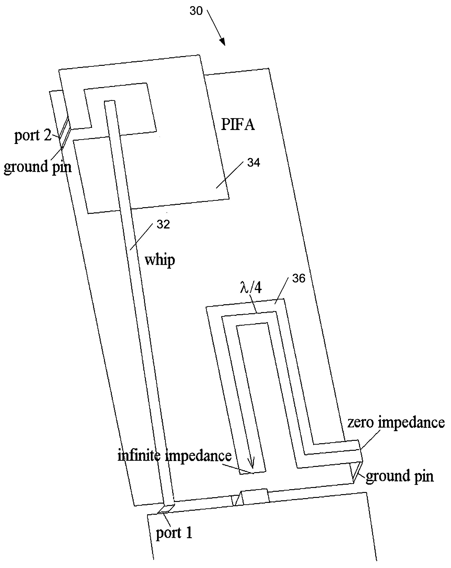
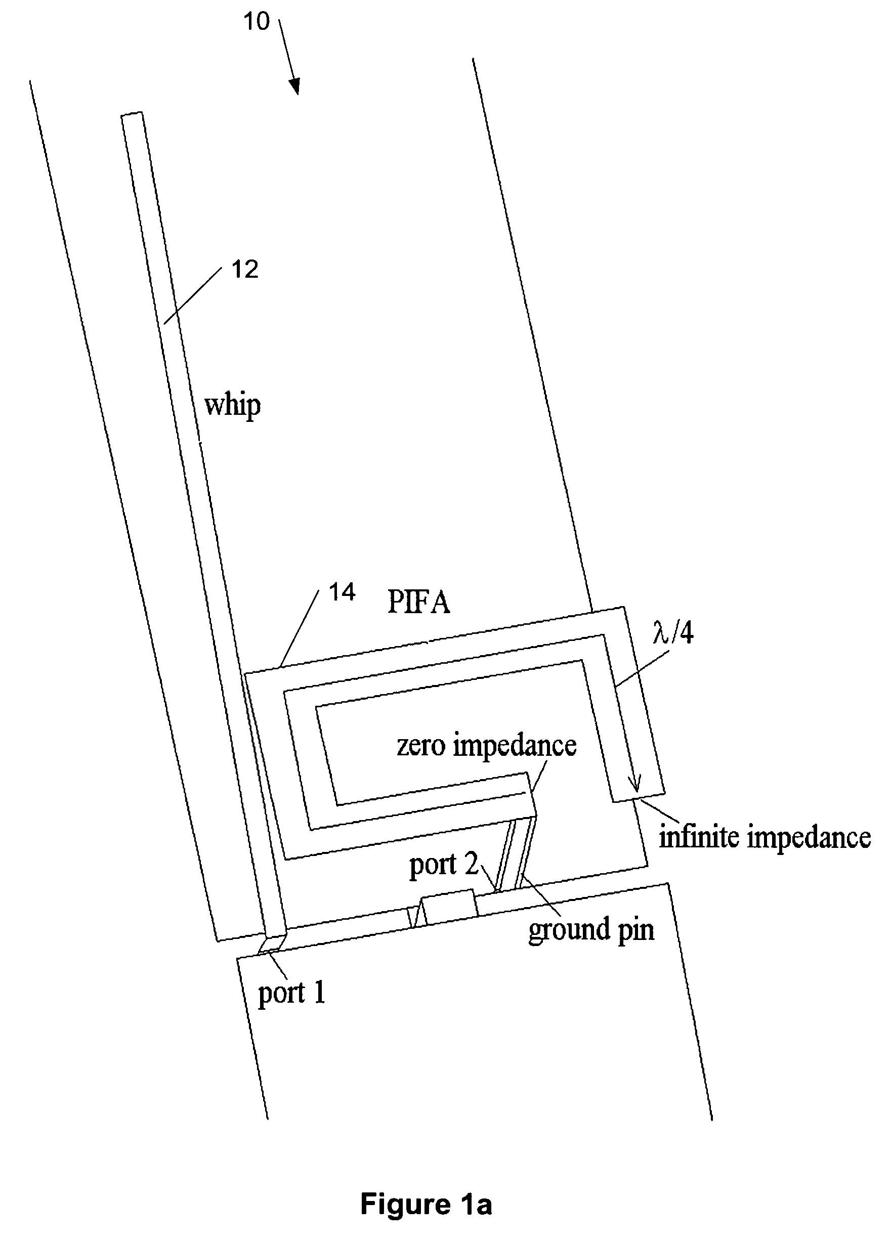
[0044]The present invention provides a new method for improving antenna isolation in an electronic communication device using grounded RF microwave elements and patterns (structures). According to embodiments of the present invention, the RF microwave element can be implemented as a short-circuited section of a quarter-wavelength long transmission line (such as a stripline), or the RF microwave element can contain a metallic coupler and two thin striplines with different lengths, or said the RF microwave element can be implemented using a balun concept. The electronic communication device can be a portable communication device, a mobile electronic device, a mobile phone, a terminal, a handset, etc.

[0045]According to an embodiment of the present invention, in a small terminal, it is possible to increase the isolation between two antennas significantly by suppressing the currents flowing along certain parts of the ground plane with a device that provides a high impedance (i.e., an imp...


PUM


Abstract

This invention describes a method for improving antenna isolation in an electronic communication device using grounded RF microwave elements and patterns (structures). According to embodiments of the present invention, the RF microwave element can be implemented as a short-circuited section of a quarter-wavelength long transmission line (such as a stripline), or the RF microwave element can contain a metallic coupler and two thin striplines with different lengths, or the RF microwave element can be implemented using a balun concept.

Description

CROSS REFERENCE TO RELATED APPLICATION[0001]This application claims priority from U.S. Provisional Patent Application Ser. No. 60 / 603,459 filed Aug. 20, 2004.TECHNICAL FIELD[0002]This invention generally relates to antennas and more specifically to improving an antenna isolation in handsets or wireless communication devices.BACKGROUND ART[0003]Mutual coupling means the electromagnetic interaction of nearby antenna elements in a multi-antenna system. The currents in each element couple electromagnetically to the neighboring elements thus distorting the ideal current distributions along the elements. This causes changes in the radiation patterns and also in the input impedances of the antennas. From the RF point of view, isolation between the feeding ports of the antennas and mutual coupling are the same thing. So low isolation means high coupling causing energy transfer between the ports and, therefore, decrease in the efficiencies of the antennas. The strength of the isolation can b...

Claims


Application Information

Patent Timeline
Patent Type & Authority Patents(United States)
IPC IPC(8): H01Q1/24
CPCH01Q1/243H01Q1/48H01Q1/521H01Q1/523H01Q5/385H01Q9/0442H01Q9/30H01Q5/371H01Q9/0421H01Q1/24H01Q9/04
Inventor ARKKO, AIMOOLLIKAINEN, JANISATO, SHUNYAPANG, HAWK YIN
Owner RPX CORP
Why Eureka
Try Eureka