Arrangement for performing proton therapy

a proton beam and arrangement technology, applied in the field of arrangement for treating patients, can solve the problems of requiring a large space in the gantry, still only used to a very limited extent, etc., and achieve the effect of reducing interference and increasing the accuracy of proton beam guiding

Active Publication Date: 2008-03-25
PAUL SCHERRER INSTITUT
View PDF3 Cites 101 Cited by
  • Summary
  • Abstract
  • Description
  • Claims
  • Application Information

AI Technical Summary

Benefits of technology

[0016]An advantage of the proposed arrangement according to the invention is that at least part of the cabling can be connected from the front of the gantry, which allows a clean, local separation of the cable runs for measurement signals and monitoring sensors from the magnetic feed. This eliminates any interference between the signals, thereby also enabling the proton beam guiding accuracy to be increased, as the sensitive measurement devices are unaffected by the magnetic feeds.

Problems solved by technology

Although proton radiation therapy is advantageous particularly for the irradiation of tumors, it is still only used to a very limited extent because of high costs and the large amount of space required for such installations.
Because of the considerable beam rigidity, the gantry requires a large amount of space (using normal magnets, the minimum deflection radius which can be applied to the beam is at least 1.3 m) and is correspondingly heavy.

Method used


Image

  • Arrangement for performing proton therapy
  • Arrangement for performing proton therapy
  • Arrangement for performing proton therapy

Examples


Embodiment Construction

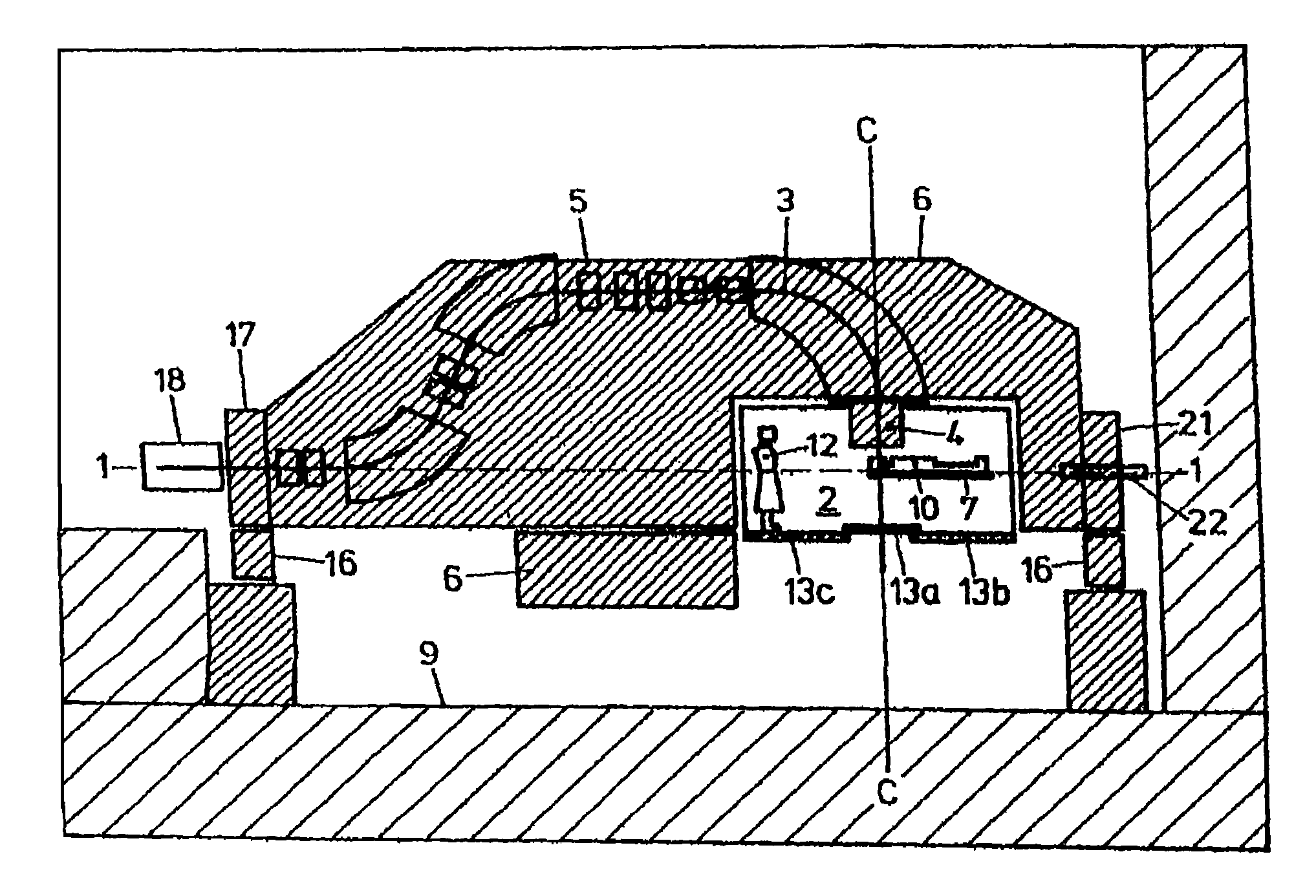
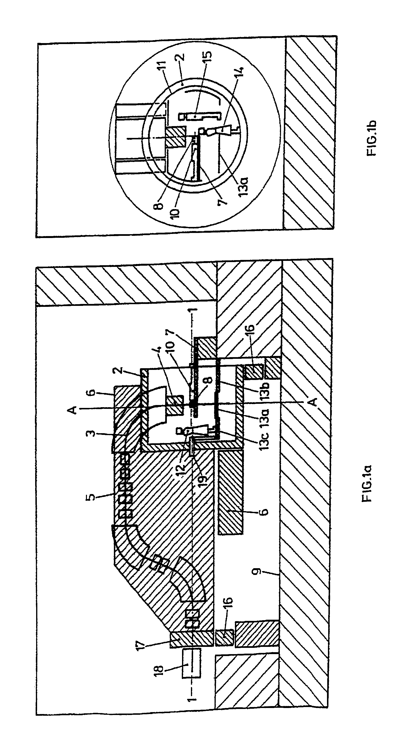
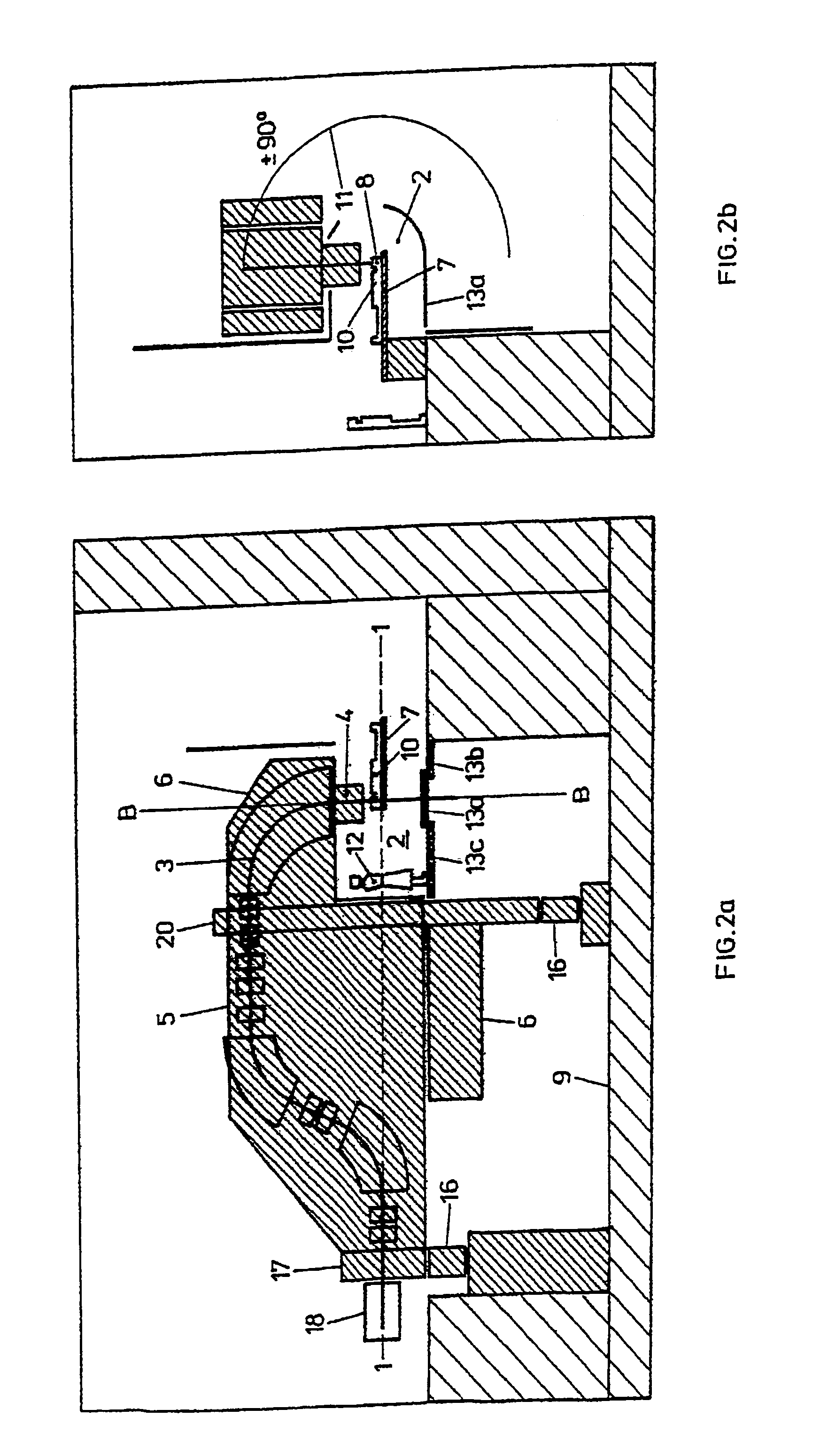
[0036]To facilitate understanding of the present invention, a currently commercially available system based on the concept that the proton beam system or gantry can be rotated completely through 360° about the longitudinal beam axis will first be described schematically with reference to FIGS. 1a and 1b.

[0037]A patient 10 is treated in a cylindrical chamber, the radiation chamber 2. The gantry 3 is installed outside the chamber. Only the last part, the so-called nozzle 4, with the measuring equipment for checking the spatial distribution of the dose, extends into the chamber (the patient must be able to be placed as near as possible to the nozzle).

[0038]The whole arrangement is carried by a rotating structure 5, including the counterweight 6 of the gantry. Item 16 shows the position of the wheels 16 on which the gantry rotates via two rollers. The rear roller 17 can be kept relatively small with a radius of approximately 1 m. The front roller is the radiation chamber itself. Item 1...


PUM


Abstract

A system for treating a patient by proton therapy, also called gantry, includes a proton beam guide involving, in particular, magnets, quadropoles, and the like and having an outlet aperture for guiding and directing the proton beam to the side in the patient that is to be treated. In addition, a patient table that cab en displaced in a controllable manner is provided for moving the patient into a desired position relative to the proton beam. The inventive proton beam guide and control device is mounted down from the patient table in the direction of the beam guide in a supported manner whereby being able to rotate or pivot about a horizontal axis.

Description

CROSS REFERENCE TO RELATED APPLICATIONS[0001]The present application is a continuation of international application PCT / CH03 / 00618, filed on Sep. 15, 2003, which designated the United States; and further claims priority to Swiss patent application 1579 / 02, filed Sep. 18, 2002; the both of which are herein incorporated by reference.BACKGROUND OF THE INVENTION[0002]The present invention relates to an arrangement for treating a patient by means of proton therapy according to the pre-characterizing clause of claim 1 as well as uses of said arrangement.[0003]Although proton radiation therapy is advantageous particularly for the irradiation of tumors, it is still only used to a very limited extent because of high costs and the large amount of space required for such installations.[0004]Proton therapy is nowadays preferably applied with the aid of a rotating beam delivery system, referred to as the gantry.[0005]The system is mounted on a rotating structure and can therefore be rotated arou...

Claims


Application Information

Patent Timeline
Patent Type & Authority Patents(United States)
IPC IPC(8): A61N5/10A61N5/00
CPCA61N5/10A61N5/1081A61N2005/1087
Inventor PEDRONI, EROS
Owner PAUL SCHERRER INSTITUT
Why Eureka
Try Eureka