Contact thermometer for body cavity

a contact thermometer and body cavity technology, applied in the field of contact thermometers for body cavities, can solve the problems of inability to use infrared radiation thermometers, inability to meet the needs of large animals, so as to achieve the effect of ensuring accuracy and speed response and further enhancing accuracy

Inactive Publication Date: 2008-05-20
FRADEN JACOB
View PDF9 Cites 23 Cited by
  • Summary
  • Abstract
  • Description
  • Claims
  • Application Information

AI Technical Summary

Benefits of technology

[0007]The contact thermometer of this invention has a temperature sensing element is attached to a moving tip whose position is automatically adapted to the location of a body cavity wall. Thus, the accuracy and speed response is assured by use of a probe having a variable geometry where the first shape of the probe exists before placing the probe into a cavity and the second shape is formed during the measurement process. The accuracy is further enhanced by use of at least two temperature sensors where at least one measures temperature of the contact area with the body cavity wall and the other temperature sensor is for compensating of the heat flow.

Problems solved by technology

A known alternative, an infrared ear thermometer, frequently is not practical for some large animals.
This limitation is mainly a result of either a hyper sensitivity at the ear area (horses) or very dirty ear canals (cows).
These factors make use of the infrared radiation thermometers quite inaccurate and, as a result, impractical.
Yet, there are two major problems in using such thermometers with the real cavities.
The first one is a large uncertainty concerning quality of a thermal contact (coupling) between the thermometer probe and a cavity wall, such as rectal tissue.
A poor thermal coupling results in a reduced accuracy—such a thermometer will read generally lower than the true temperature is.
Another problem is a speed response, which again is a result of quality of a thermal contact and a thermal capacity of the temperature probe.
In a veterinary medicine, restraining a large animal for such a long time sometimes is difficult and often expensive.

Method used


Image

  • Contact thermometer for body cavity
  • Contact thermometer for body cavity
  • Contact thermometer for body cavity

Examples


Embodiment Construction

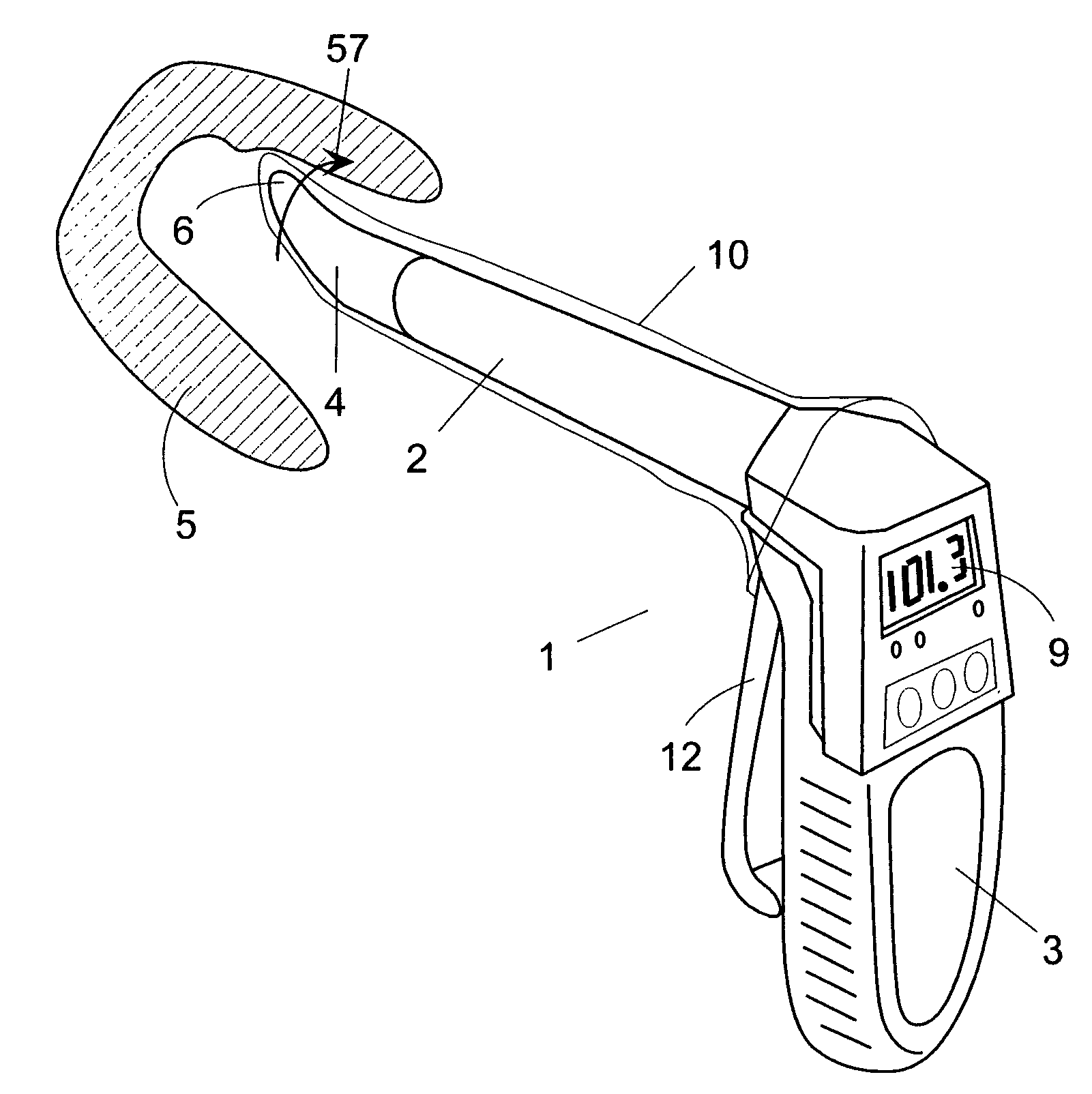
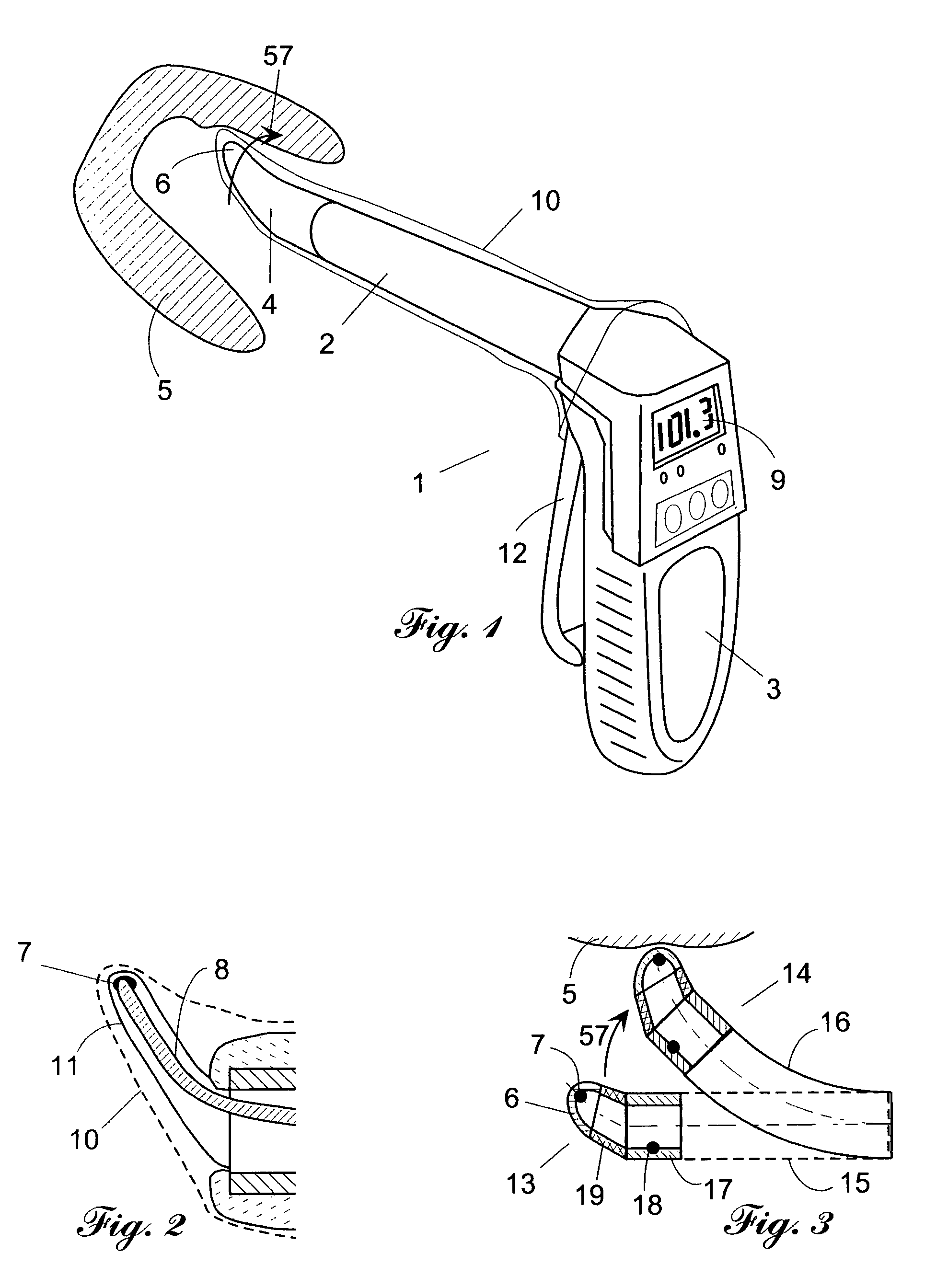
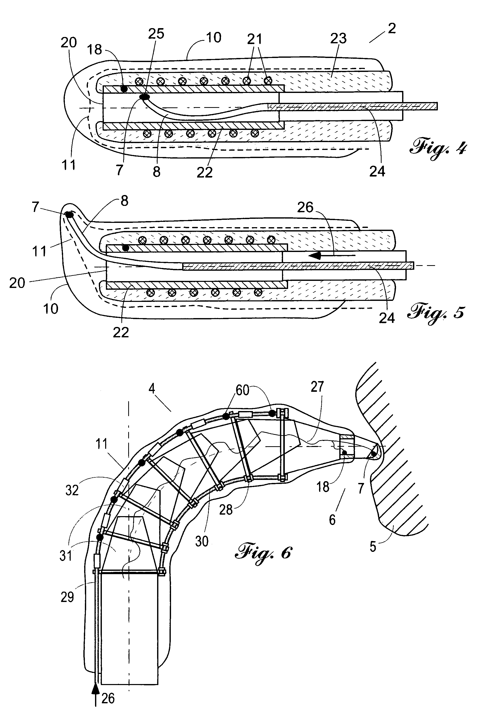
[0024]Two major issues of a cavity temperature measurement are resolved in the present invention by providing several solutions. The first issue is making a reliable thermal contact between a sensing element (temperature sensor) and the body cavity wall. The second issue is assuring a fast measurement time.

[0025]The first issue with temperature measurement is to assure that a sensing element is either in thermal equilibrium with a measured surface or it's thermal response is moving fast toward such an equilibrium. To address this issue properly, it is essential to make a good and reliable thermal contact between a sensor and an inner wall of the body cavity. A lack of a good thermal coupling inadvertently will result in reduced accuracy and a longer response time. Since a body cavity generally may have an unpredictable shape and size, a means for a fast and reliable attachments of a temperature sensor to the cavity inner wall under these conditions shall be provided. The present inv...


PUM

PropertyMeasurementUnit
temperatureaaaaaaaaaa
thermal massaaaaaaaaaa
pressureaaaaaaaaaa

Abstract

A contact thermometer for determining-temperature of an inner wall of a cavity, where accuracy and speed response is assured by use of a probe having a variable geometry where the first shape of the probe exists before and during placing the probe into a cavity and the second shape is formed during the measurement process. The temperature measuring tip of the probe makes an intimate thermal contact with an inner wall of a cavity after the second geometrical shape is assumed. The accuracy is assured by use of at least two temperature sensors while the speed response is improved by taking at least two readings, from one temperature sensor.

Description

[0001]This invention claims the benefit of priority to Provisional U.S. Patent Application No. 60 / 478,362 filed on Jun. 16, 2003 and relates to devices for measuring temperature, more specifically to contact thermometers, primarily intended for medical and veterinary applications.FIELD OF INVENTIONDescription of Prior Art[0002]A body cavity thermometer (BCT) is a device capable of measuring temperature from a body cavity. An example of a body cavity is rectum of a large animal, such as a horse or cow. In a general veterinary practice, a rectum, if not terribly convenient, yet it's the only practical site for quick assessing the animal's internal body temperature. A known alternative, an infrared ear thermometer, frequently is not practical for some large animals. This limitation is mainly a result of either a hyper sensitivity at the ear area (horses) or very dirty ear canals (cows). These factors make use of the infrared radiation thermometers quite inaccurate and, as a result, imp...

Claims


Application Information

Patent Timeline
Patent Type & Authority Patents(United States)
IPC IPC(8): G01K1/00G01J5/00G01K1/20G01K7/00G01K7/42G01K13/00
CPCG01K1/20G01K7/42G01K13/002G01K13/20
Inventor FRADEN, JACOB
Owner FRADEN JACOB
Why Eureka
Try Eureka