Oil scraper ring for pistons of internal combustion engines

a technology for internal combustion engines and scraper rings, which is applied in mechanical equipment, braking systems, transportation and packaging, etc., can solve the problems of high friction power during engine operation, worsen the degree of effectiveness of internal combustion engines, and high surface pressure against the working surfaces of lamellae, so as to improve the oil wiping effect, reduce friction, and reduce the wear of the working surface.

Inactive Publication Date: 2008-07-08
MAHLE GMBH
View PDF19 Cites 6 Cited by
  • Summary
  • Abstract
  • Description
  • Claims
  • Application Information

AI Technical Summary

Benefits of technology

[0006]It is the task of the invention to indicate a multi-part oil wiping ring for a piston of an internal combustion engine, which has an improved oil wiping effect as compared with the known state of the art, at reduced friction and a reduced wear of the working surface.
[0010]By means of the working surface configuration according to the invention, and the placement of the lamella in the spreading spring configured according to the invention, a reduction in the friction power of the oil wiping ring as a whole is achieved, by means of more advantageous hydrodynamic conditions at the lamella, without any reduction in tangential force, as a function of the stroke movement of the piston, whereby the oil wiping function is maintained to its full extent, with the change in the stroke movement of the piston. The reduction in the friction power results in an improvement of the degree of effectiveness of the engine, or the oil wiping behavior can be improved by means of an increase in the tangential force, with an unchanged friction power level. Furthermore, a reduction in the axial height of the total ring package can be achieved, as compared with ring packages according to the state of the art.

Problems solved by technology

However, this results in a high surface pressure against the working surfaces of the lamellae, and therefore also a high friction power during engine operation.
This friction power worsens the degree of effectiveness of the internal combustion engine and accordingly increases the fuel consumption.
These previously known embodiments, however, relate to compression rings, whose requirements with regard to surface pressure are very low, while oil wiping rings demand great surface pressures.

Method used


Image

  • Oil scraper ring for pistons of internal combustion engines
  • Oil scraper ring for pistons of internal combustion engines

Examples


Embodiment Construction

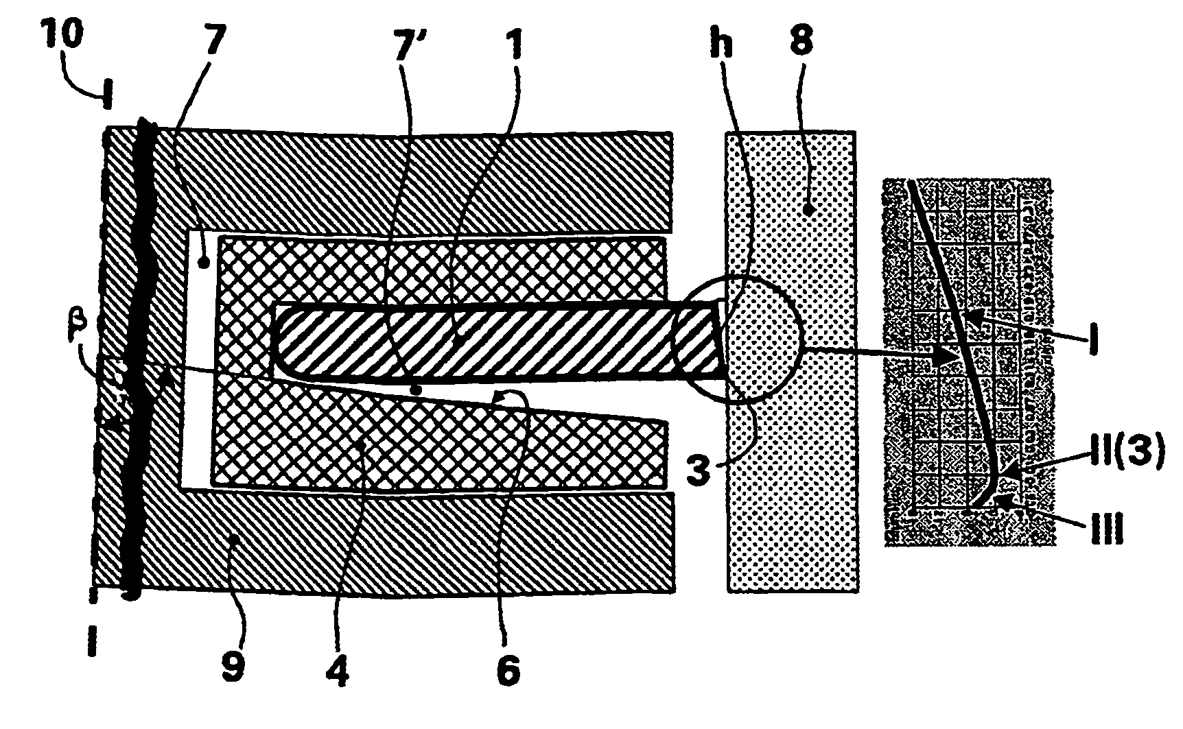
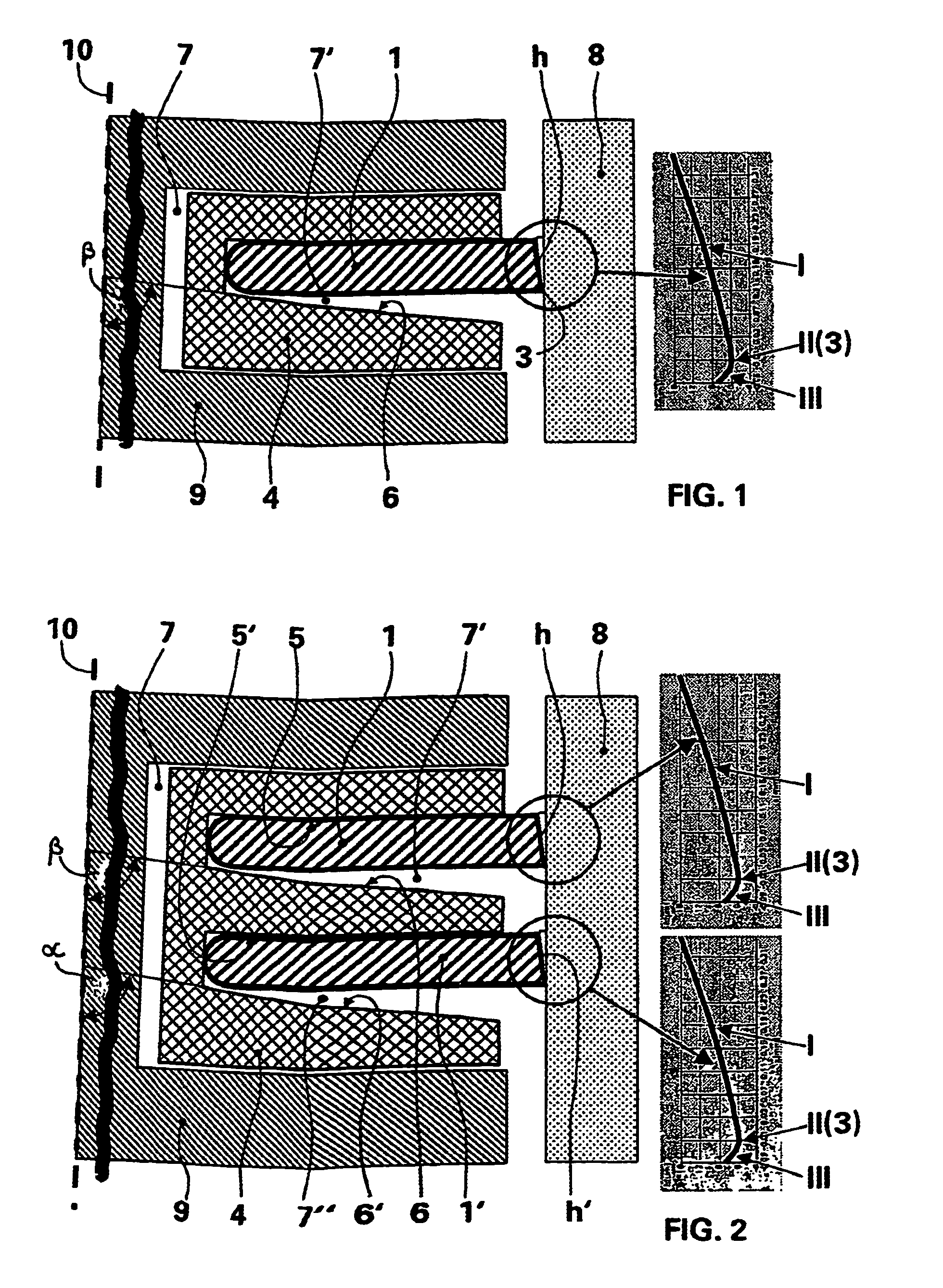
[0015]As is evident from FIG. 1, an oil wiping ring consists of a lamella 1 and a spreading spring 4 that presses the lamella radially against a cylinder wall 8. The spreading spring 4 is inserted into a ring groove that has ring groove walls oriented at 90° degrees relative to the piston axis 10, and possesses an outer shape and size that corresponds to the ring groove. The spreading spring has a spring groove 7′ having a spring groove wall 5 that represents the side facing the piston crown side, and a spring groove wall 6 that represents the side facing away from the piston crown. According to the invention, the spring groove wall 5 that faces the piston crown side is disposed oriented at an angle of 90° relative to the piston axis 10, whereby the spring groove wall 6 that faces away from the piston crown runs at an angle β inclined away from the piston crown, up to the outside spring circumference. Preferably, the angle β amounts to 85° to 87° degrees of angle.

[0016]According to ...


PUM


Abstract

The invention relates to an oil scraper ring for pistons of internal combustion engines. The oil scraper ring comprises a disc that is provided with parallel flanks and a bearing surface having an asymmetrical crowned form with a vertex line extending over the periphery of the disc. A bracing spring arranged in a ring groove of the piston and comprising a spring groove side opposing the piston head and a spring groove side facing the piston head presses the disc radially against the friction and the abrasion of the bearing surface. To this end, at least one of the spring groove sides extends at an angle in relation to the piston axis in such a way that it is radially outwardly inclined to the bracing spring end oriented towards the cylinder, the bearing surface of the disc being embodied in such a way that it corresponds to an almost worn end contour in the started engine state, and, when the oil scraper ring is mounted in the piston, the vertex line of the bearing surface is oriented in the direction of the ring groove side opposing the piston head.

Description

CROSS REFERENCE TO RELATED APPLICATIONS[0001]Applicant claims priority under 35 U.S.C. §119 of German Application No. 103 40 302.7 filed September 2, 2003. Applicant also claims priority under 35 U.S.C. §365 of PCT / DE2004 / 001961 filed Sep. 2, 2004. The international application under PCT article 21(2) was not published in English.BACKGROUND OF THE INVENTION[0002]The invention relates to an oil wiping ring for pistons of internal combustion engines, having a lamella consisting of strip steel, provided with parallel walls, whose working surface has a barrel-shaped asymmetrical shape, having a vertex line that extends over the circumference of the lamella, whereby a spreading spring disposed in a ring groove of the piston and having one spring groove wall facing away from the piston crown side and one spring groove wall facing the piston crown side presses the lamella radially against the cylinder wall.[0003]In order to prevent too much motor oil from getting into the combustion chambe...

Claims


Application Information

Patent Timeline
Patent Type & Authority Patents(United States)
IPC IPC(8): F16J9/20F16J9/06
CPCF16J9/206F16J9/065F16J9/06F16J9/12
Inventor FIEDLER, ROLF-GERHARD
Owner MAHLE GMBH
Why Eureka
Try Eureka