Ankle clamp assembly for an inversion table

Inactive Publication Date: 2008-07-15
LIFEGEAR TAIWAN
View PDF5 Cites 11 Cited by
  • Summary
  • Abstract
  • Description
  • Claims
  • Application Information

AI Technical Summary

Benefits of technology

[0010]The main objective of the present invention is to provide an ankle clamp assembly for an inve

Problems solved by technology

3. The ankle clamp assembly will make manuf

Method used


Image

  • Ankle clamp assembly for an inversion table
  • Ankle clamp assembly for an inversion table
  • Ankle clamp assembly for an inversion table

Examples


Embodiment Construction

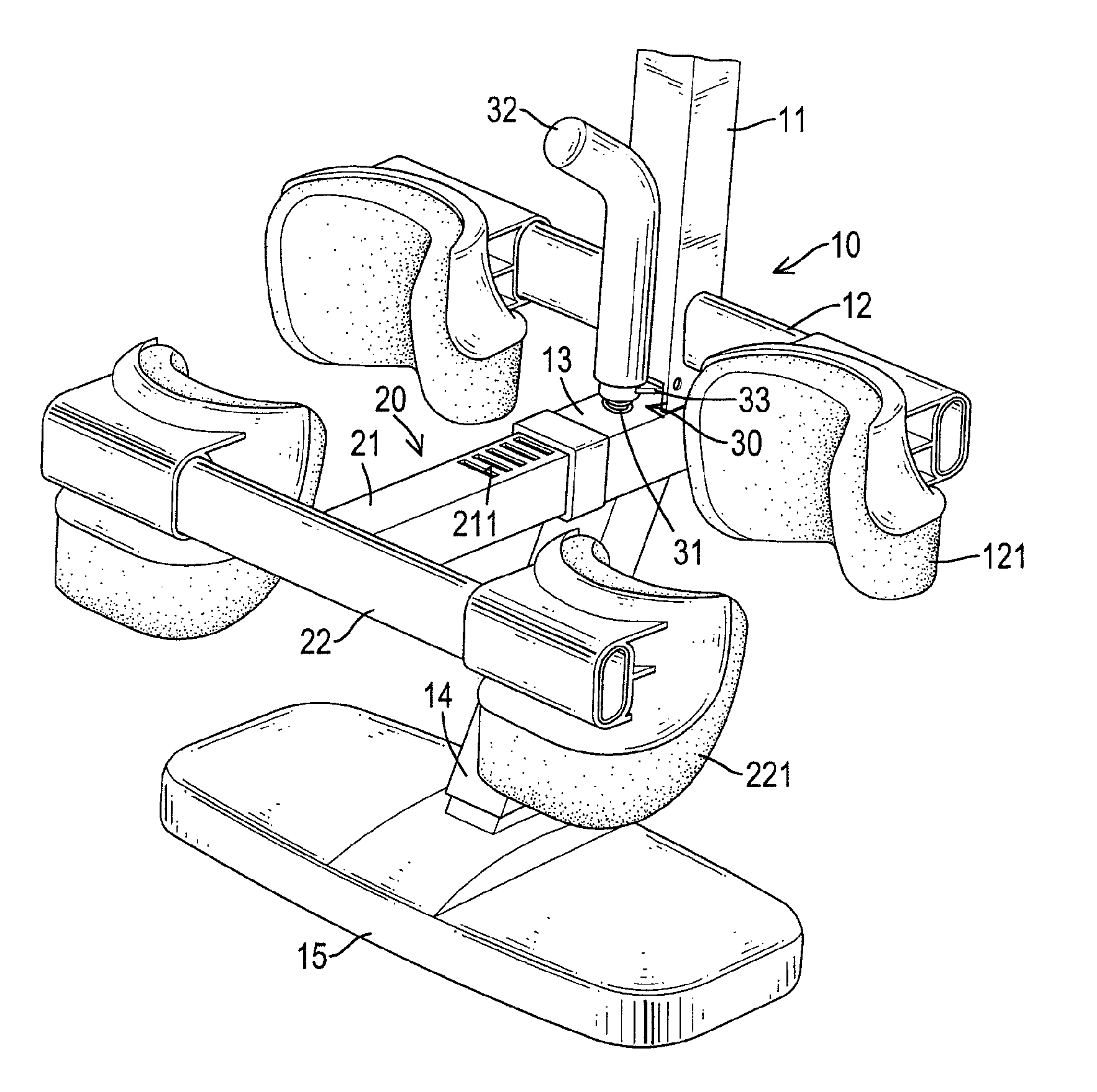
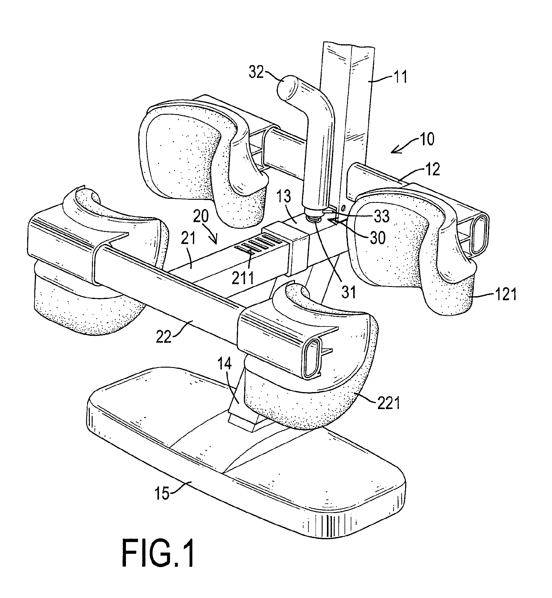
[0018]With reference to FIGS. 1 to 3, an ankle clamp assembly for an inversion table having a table comprises a stationary frame (10), an adjustable frame (20) and an operating device (30).

[0019]The stationary frame (10) is connected securely to the table of the inversion table and has a longitudinal beam (11), a transverse beam (12), an optional extension arm (14) and an optional footrest (15).

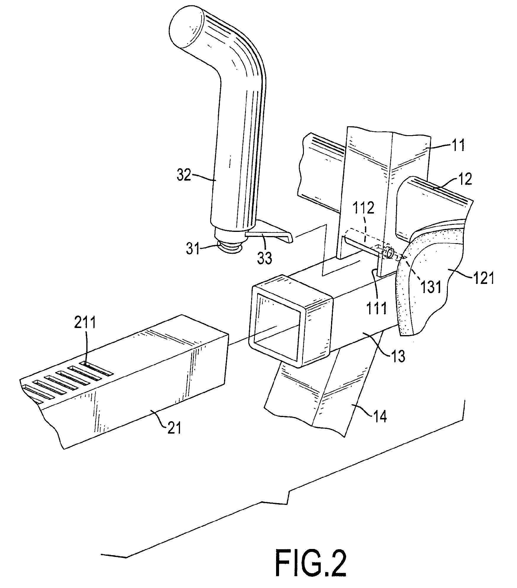
[0020]The longitudinal beam (11) may be tubular and non-circular, is connected securely to the table of the inversion table and has a top end, a bottom end, a front surface, two sidewalls, a chamber, a recess (111), a latch rod (112) and a mounting arm (13). The top end of the longitudinal beam (11) is connected securely to the table of the inversion table. The bottom end of the longitudinal beam (11) is open. The chamber is formed inside the longitudinal beam (11) and communicates with the bottom end. The recess (111) is formed through the front surface of the longitudinal beam (11) at the b...


PUM


Abstract

An ankle clamp assembly for an inversion table has a stationary frame, an adjustable frame and an operating device. The stationary frame has a longitudinal beam and a transverse beam. The longitudinal beam is connected to the inversion table and has a recess, a latch rod and a mounting arm. The mounting arm is connected to the longitudinal beam and has a stationary latch hole. The adjustable frame is movably connected to the stationary frame and has an adjusting arm and a pressing arm. The adjusting arm extends through the mounting arm and has multiple elongated latch holes. The operating device is connected to the stationary frame, engages the adjustable frame and has a spring, a handle and a latch lever. The latch lever is attached transversely to the handle, extends through the recess into an elongated latch hole corresponding to the stationary latch hole.

Description

BACKGROUND OF THE INVENTION[0001]1. Field of the Invention[0002]The present invention relates to an ankle clamp assembly, and more particularly to an ankle clamp assembly for an invention table, which can be adjusted easily and quickly.[0003]2. Description of Related Art[0004]With reference to FIG. 5, a conventional inversion table (50) holds a person's body to relax or relieve back pain, and has a mounting bracket (51), a table (52) and an ankle clamp assembly (53). The mounting bracket (51) has two connecting plates, a front frame, a rear frame and two folding links. Each connecting plate has multiple mounting holes. The front frame is U-shaped and has two ends. The ends are connected pivotally to the mounting holes respectively in the connecting plates. The rear frame is U-shaped and has two top ends. The top ends are connected securely to the mounting holes respectively in the connecting plates. The folding links are connected between the front and rear frames to hold the mounti...

Claims


Application Information

Patent Timeline
IPC IPC(8): A63B22/14
CPCA61H1/0218Y10T403/32483A61H2203/0493A61H2201/1642
Inventor CHEN, SHI-LIN
Owner LIFEGEAR TAIWAN
Why Eureka
Try Eureka