Toroidal non-glary luminaire

a non-glare, luminaire technology, applied in lighting support devices, lighting and heating apparatuses, instruments, etc., can solve the problems of difficult adjusting the lighting direction of existing luminaires, affecting the aesthetics of luminaires, and many conventional luminaires suffering from glare problems, etc., to achieve the effect of simplifying the installation process and quick and easy adjustment of luminaire angl

Active Publication Date: 2022-01-18
ABL IP HLDG
View PDF15 Cites 1 Cited by
  • Summary
  • Abstract
  • Description
  • Claims
  • Application Information

AI Technical Summary

Benefits of technology

[0002]Embodiments of the present invention are directed to luminaires, adjustment mechanisms, and installation techniques. In particular embodiments of the invention are directed to halo-shaped luminaires that produce uniform light. Embodiments are also directed to magnetic adjustment mechanisms that allow the luminaires to be pivoted and / or otherwise manipulated to adjust an angle of the light emitted from the luminaire. These magnetic adjustment mechanisms enable a user to quickly and easily adjust the angle of the luminaire. Additionally, these adjustment mechanisms provide solutions that enable a user to quickly orient the luminaire in a directly downward relative to a supporting structure. Embodiments further provide a luminaire housing that simplifies the installation processes when luminaires are installed in ceiling recesses. Such housings employ spring-biased locking arms to secure the housing within a recess once inserted above a top surface of a ceiling.

Problems solved by technology

Many conventional luminaires suffer from problems related to glare.
This glare is uncomfortable to the human eye and makes the luminaire less aesthetically pleasing.
Adjusting a lighting direction of existing luminaires may be difficult, especially if a user wants to position the luminaire to direct light in a directly downward position, or if a user wishes to adjust the luminaire quickly with a single hand.
Additionally, when installed in recessed lighting applications, oftentimes conventional luminaires can be difficult and / or dangerous to install.
This installation is often performed while the user is standing on a ladder, making the installation with a single hand even more dangerous.

Method used


Image

  • Toroidal non-glary luminaire
  • Toroidal non-glary luminaire
  • Toroidal non-glary luminaire

Examples


Embodiment Construction

[0037]The subject matter of embodiments of the present invention is described here with specificity to meet statutory requirements, but this description is not necessarily intended to limit the scope of the claims. The claimed subject matter may be embodied in other ways, may include different elements or steps, and may be used in conjunction with other existing or future technologies. This description should not be interpreted as implying any particular order or arrangement among or between various steps or elements except when the order of individual steps or arrangement of elements is explicitly described.

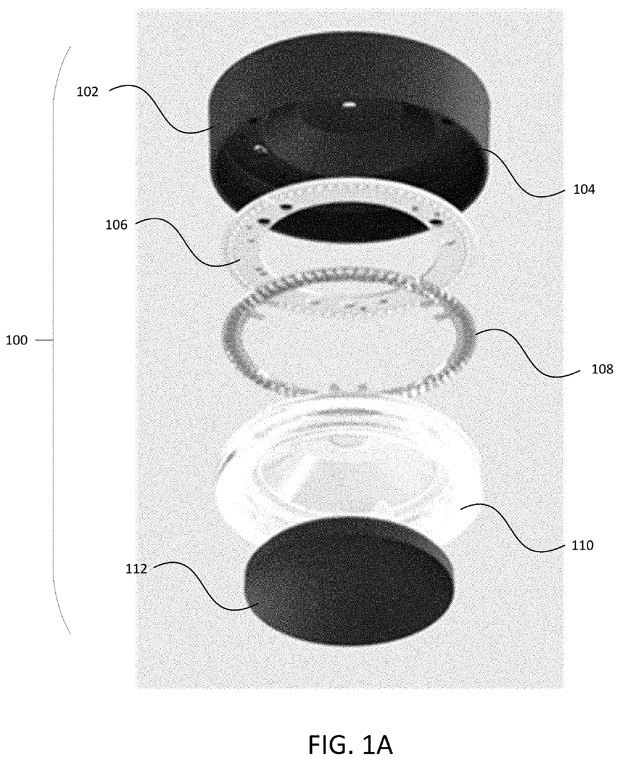
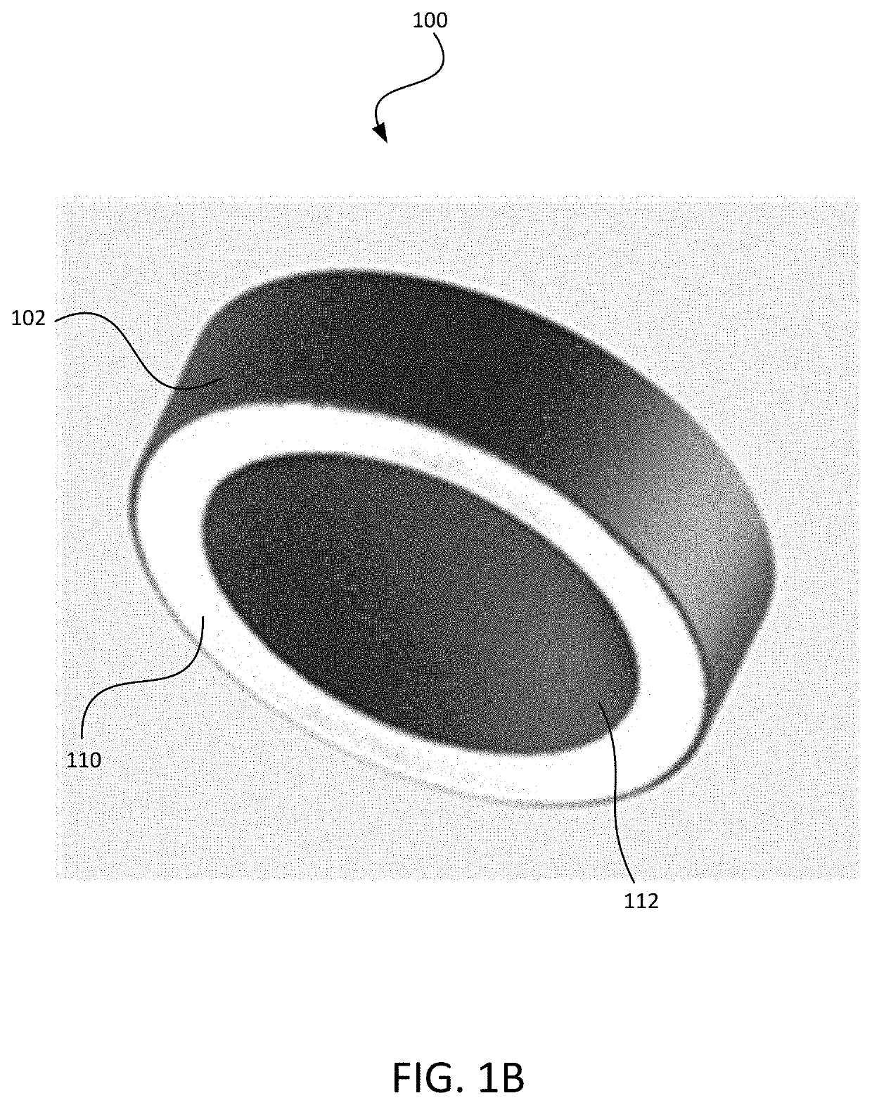
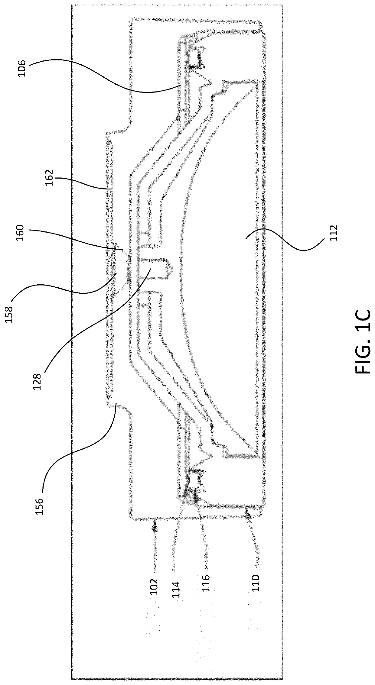
[0038]Embodiments of the present disclosure are directed to luminaires that produce a visually uniform light ring. Embodiments achieve these effects using a combination of features. For example, in some embodiments, a toroidal integrated optic (TIO), which is made up of a TIR lens that is coupled with a light guide, may be used to generate halo shaped light (however, it will be ...


PUM

PropertyMeasurementUnit
beam angleaaaaaaaaaa

Abstract

A non-glare luminaire includes a toroidal-shaped light engine having light emitting diodes (LEDs) disposed about the light engine in a radial pattern. The light engine has an axial direction that is at least substantially orthogonal to the surface of the light engine. An anti-glare ring is disposed proximate the light engine and includes reflectors arranged in a radial pattern. Each reflector is configured to reflect tangentially oriented light from at least one of the LEDs substantially along the axial direction. The luminaire also includes a toroidal integrated optic (TIO), which is made up of a total internal reflectance (TIR) lens that is coupled with a light guide. The TIO optic has a toroidal lens portion having a light entrance side that receives light from the LEDs and the reflectors. The optic collimates the light received from the LEDs and the reflectors and emit the light via a light exit side.

Description

BACKGROUND OF THE INVENTION[0001]Many conventional luminaires suffer from problems related to glare. This glare is uncomfortable to the human eye and makes the luminaire less aesthetically pleasing. Adjusting a lighting direction of existing luminaires may be difficult, especially if a user wants to position the luminaire to direct light in a directly downward position, or if a user wishes to adjust the luminaire quickly with a single hand. Additionally, when installed in recessed lighting applications, oftentimes conventional luminaires can be difficult and / or dangerous to install. This is due to the need for the user to support the luminaire and / or housing within the ceiling recess while attempting to wire the luminaire into a structure's power system. This installation is often performed while the user is standing on a ladder, making the installation with a single hand even more dangerous. Solutions to these and other problems are desired.BRIEF SUMMARY OF THE INVENTION[0002]Embod...

Claims


Application Information

Patent Timeline
Patent Type & Authority Patents(United States)
IPC IPC(8): F21V13/12F21V7/00F21V5/04F21V29/70F21V11/14F21V8/00F21V21/14F21V17/10F21V17/02F21V21/04F21S8/02F21Y115/10
CPCF21V13/12F21S8/026F21V5/043F21V7/0058F21V7/0083F21V11/14F21V17/02F21V17/105F21V21/047F21V21/14F21V29/70G02B6/0038F21Y2115/10G02B6/0011F21V21/044F21V7/0091F21Y2103/33F21V5/045
Inventor VERNIER, ETIENNETAMEH, TAHEREH AHMADITHOMAS-BERUBE, LOUISZYLSTRA, DIRKPOULIN, JEROME
Owner ABL IP HLDG
Why Eureka
Try Eureka