Anti-islanding method and system for distributed power generation systems

a distributed power generation and anti-islanding technology, applied in the direction of electrical equipment, ac network circuit arrangements, single network parallel feeding arrangements, etc., can solve problems such as the cut-off of inverters, and achieve the effect of rapid variation

Active Publication Date: 2008-08-05
MARICI HLDG THE NETHERLANDS BV
View PDF15 Cites 71 Cited by
  • Summary
  • Abstract
  • Description
  • Claims
  • Application Information

AI Technical Summary

Benefits of technology

[0019]One object of the present invention is to provide a method and a system that improves the known methods and devices for the prevention of islanding. Generally, the invention is based on the concept of detecting an islanding condition according to any one of the conventional methods available. However, instead of causing an immediate de-activation of the inverter in response to detection of an islanding parameter, the present invention causes a variation in the power level delivered by the inverter towards the load and toward

Problems solved by technology

Whatever the type (voltage or frequency) and sign (increase or reduction) of the parameter change induced by the variation in power delivered, it will result in cu

Method used


Image

  • Anti-islanding method and system for distributed power generation systems
  • Anti-islanding method and system for distributed power generation systems
  • Anti-islanding method and system for distributed power generation systems

Examples


Embodiment Construction

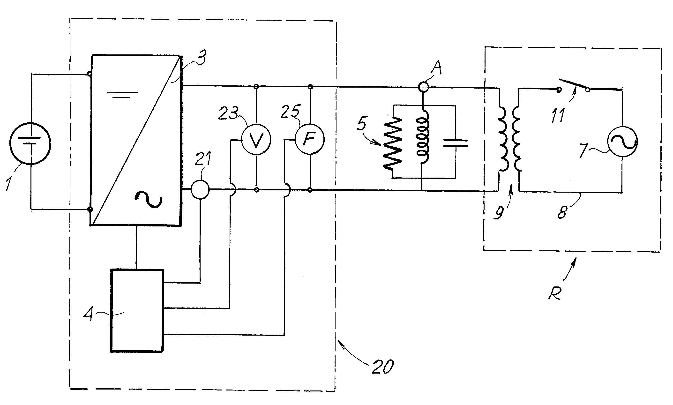
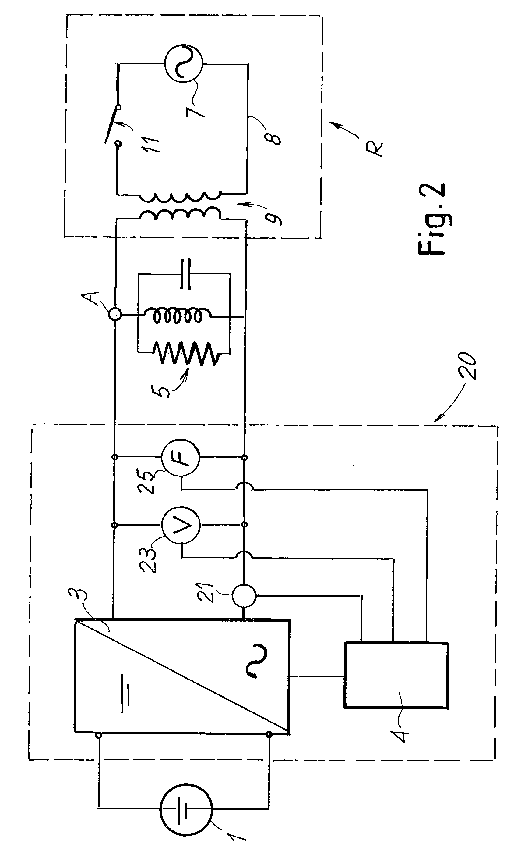
[0037]FIG. 2 is a block and schematic diagram of a power system that embodies the invention. The power system includes a power source 1, for example a battery of photovoltaic cells, which generates a direct current. This must be converted into alternating current to power a local load or to be fed into the electricity distribution grid. For this purpose the system further includes an inverter 3 controlled by a management and control device 4. A load 5 is connected to the output of the inverter 3, which is schematically represented as a load comprising a resistive component, a capacitive component and an inductive component. The connection point of the inverter 3 to the load is designated by the letter A. The inverter 3 is also connected in parallel to the electrical distribution grid, indicated overall by R and schematically represented by an alternating voltage source 7, by a distribution line 8, by a transformer 9, and by a switch 11 for disconnection of the alternating voltage so...


PUM


Abstract

An electrical power supply system connected to an electrical grid, includes at least one source of electrical power, an inverter which receives power from the electrical source and delivers power to a local load, and a connection to the electrical grid. The system also includes a control unit for controlling the inverter, which interrupts the delivery of power by the inverter when at least one electrical parameter of the system exceeds a threshold value. The system also includes anti-islanding logic which detects at least one symptom of an islanding condition of the system and, when the symptom is detected, to cause a variation in the power level delivered by the inverter.

Description

[0001]A portion of the disclosure of this patent document contains material that is subject to copyright protection. The copyright owner has no objection to the facsimile reproduction by anyone of the patent document or the patent disclosure, as it appears in the U.S. Patent and Trademark Office patent file or records, but otherwise reserves all copyright rights whatsoever.CROSS-REFERENCES TO RELATED APPLICATIONS[0002]Not ApplicableSTATEMENT REGARDING FEDERALLY SPONSORED RESEARCH OR DEVELOPMENT[0003]Not ApplicableREFERENCE TO SEQUENCE LISTING OR COMPUTER PROGRAM LISTING APPENDIX[0004]Not ApplicableBACKGROUND OF THE INVENTION[0005]The present invention generally concerns the distributed generation of electricity by means of alternative sources such as photovoltaic cells, fuel cells, wind generators and the like, or via conventional sources such as autogenous units with small internal combustion engines for the local generation of electricity. More particularly, this invention pertain...

Claims


Application Information

Patent Timeline
IPC IPC(8): H02J1/00
CPCH02J3/38H02J2003/388H02J3/388
Inventor NOCENTINI, DANIOMACERINI, SAURO
Owner MARICI HLDG THE NETHERLANDS BV
Why Eureka
Try Eureka