Apparatus for power circuit of light emitting diode

a technology of light-emitting diodes and power circuits, which is applied in the direction of lighting and heating apparatus, lighting support devices, instruments, etc., can solve the problems of reducing the use rate of driving circuits, occupying the whole circuit, and all circuit structures to become more complex, so as to reduce the difficulty of product technology, reduce the occupation of the whole electrical circuit, and avoid the consumption of electrical energy.

Inactive Publication Date: 2008-08-05
CHANG GUNG UNIVERSITY
View PDF5 Cites 11 Cited by
  • Summary
  • Abstract
  • Description
  • Claims
  • Application Information

AI Technical Summary

Benefits of technology

[0013]The invention can reduce the amount of the electrical source adaptors; can also reduce complexity for the electrical circuit structure. Furthermore, the number of driving circuit connection lines, connection components, and different sorts of terminals all can be highly reduced. It makes the occupation for the whole electrical circuits to be much smaller, to reduce the difficulty for the product technology, also to reduce the production cost.
[0018]Therefore, the invention can avoid the electrical energy consume for changing from the direct current to the alternating current, also can reduce request for the amounts of circuit elements and various connection elements, so that it can reduce the occupation for the whole electrical circuits much more smaller, reducing the difficulty for the product technology, also for reducing the production cost.

Problems solved by technology

It will cause all circuit structures to become more complex, and the use rate of driving circuit will be lower.
It will make the occupation of whole circuit to be bigger, to increase the difficulty for the production technology; also the manufacture cost will be higher.

Method used


Image

  • Apparatus for power circuit of light emitting diode
  • Apparatus for power circuit of light emitting diode

Examples


Embodiment Construction

[0021]The following is a description of the present invention. The invention firstly will be described with reference to one exemplary structure. Some variations will then be described as well as advantages of the present invention. A preferred method of fabrication will then be discussed. An alternate, asymmetric embodiment will then be described along with the variations in the process flow to fabricate this embodiment.

[0022]Due to inconvenience caused by the conventional technology, the main purpose for this invention is to avoid the use of the power adaptor and reducing the element cost by using the series connection method for the whole L.E.D. apparatus. The invention will be described as the followings:

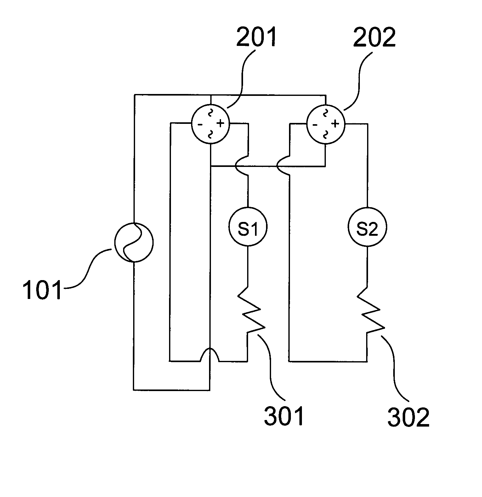
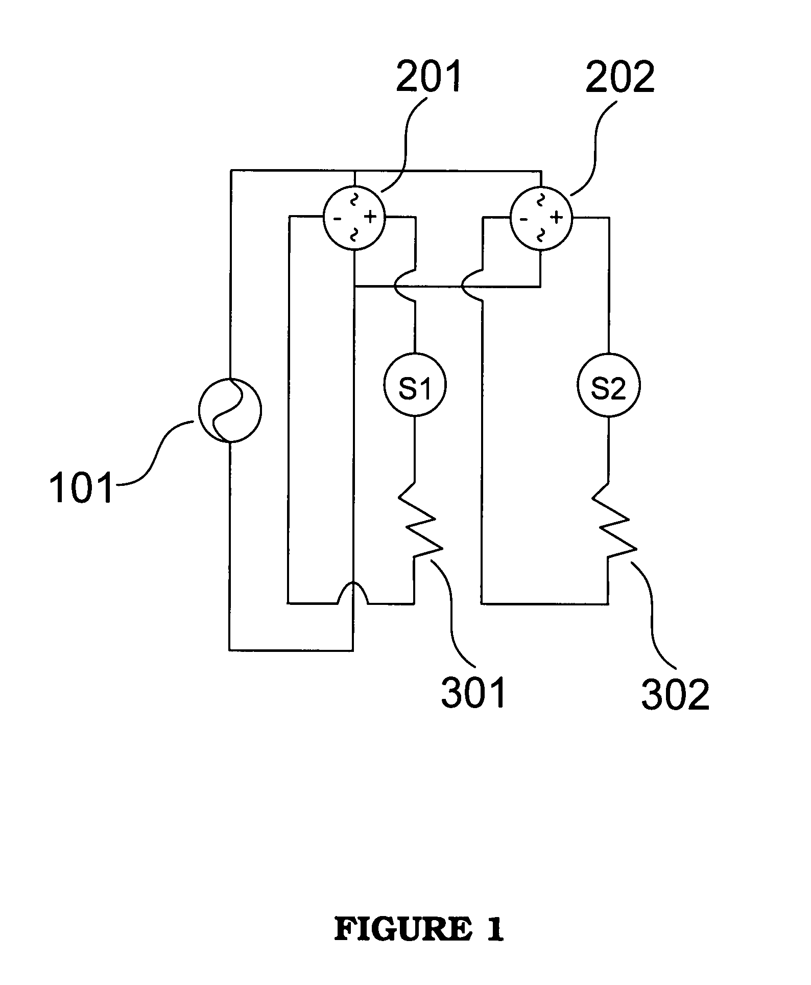
[0023]As FIG. 1 shows, the first L.E.D. composition unit apparatus can be connected with the full-wave bridge rectifier 201, the S1 L.E.D. group, as well as the current-limiting resistor 301 using the series connection method.

[0024]Further, as FIG. 1 shows, the second L.E.D. com...


PUM


Abstract

The invention is set for connecting L.E.D., bridging rectifier and AC / DC power transformer by using series connection method, also the main purpose is for saving energy and reducing the cost of electronic components. The first apparatus is built by first bridge rectifier, first L.E.D. group and first current-limiting resistor using the series connection method. The second apparatus is built by second bridge rectifier, second L.E.D. group and second current-limiting resistor using the series connection method. Then, finally the previous two apparatus will be connected each other by using parallel connection method to the AC / DC power source.

Description

BACKGROUND OF THE INVENTION[0001]1. Field of the Invention[0002]The invention relates to an electrical circuit apparatus for L.E.D., more particularly for applying to an alternating current (A.C.) power circuit apparatus for L.E.D.[0003]2. Description of the Prior Art[0004]At the present day, light emitting (L.E.D.) device is a revolution-effect production after the electronic transistor and the laser L.E.D. appeared by the semiconductor technology development. The lifetime of L.E.D. light bulb can be longer than the normal light bulb about 50 to 100 folds. Also, the power consumption of L.E.D. is about ⅓ to ⅕ than the normal light bulb. Therefore, in the 21st century, it is possible to become a new lighting source coupled with electricity saving and green concept, to be taken over the tungsten-filament lamp and the mercury lamp.[0005]The related peripheral technology for the L.E.D. including the lighting source research and development technology for the L.E.D., driving force tech ...

Claims


Application Information

Patent Timeline
Patent Type & Authority Patents(United States)
IPC IPC(8): G09G3/10
CPCG09G3/14H05B33/0809Y02B20/348H05B45/382Y02B20/30Y10S362/80
Inventor LIN, RAY-MINGYU, SHENG-FUWENG, WEI-TSELIN, YUNG-HSIANG
Owner CHANG GUNG UNIVERSITY
Why Eureka
Try Eureka