Electronic ballast having a flyback cat-ear power supply

a technology of cat-ear power supply and electronic ballast, which is applied in the direction of electric variable regulation, process and machine control, instruments, etc., can solve the problems of large and costly components of such a boost converter, unwanted harmonics and undesirable total harmonic distortion, and large power dissipation of resistors

Inactive Publication Date: 2008-10-07
LUTRON TECH CO LLC
View PDF20 Cites 34 Cited by
  • Summary
  • Abstract
  • Description
  • Claims
  • Application Information

AI Technical Summary

Problems solved by technology

In order to handle the amount of current required to drive the lamp at high end (i.e. at or near 100% light intensity), the components of such a boost converter are typically large and costly.
This results in the ballast drawing an input current 240 from the AC mains only during a relatively large duration of each line half-cycle centered about the peak of the line voltage, which allows for unwanted harmonics and undesirable total harmonic distortion (THD).
Additionally, in order to obtain the appropriate shape of the input current waveform, the power dissipated by the resistor may be very large.

Method used


Image

  • Electronic ballast having a flyback cat-ear power supply
  • Electronic ballast having a flyback cat-ear power supply
  • Electronic ballast having a flyback cat-ear power supply

Examples


Embodiment Construction

[0031]The foregoing summary, as well as the following detailed description of the preferred embodiments, is better understood when read in conjunction with the appended drawings. For the purposes of illustrating the invention, there is shown in the drawings an embodiment that is presently preferred, in which like numerals represent similar parts throughout the several views of the drawings, it being understood, however, that the invention is not limited to the specific methods and instrumentalities disclosed.

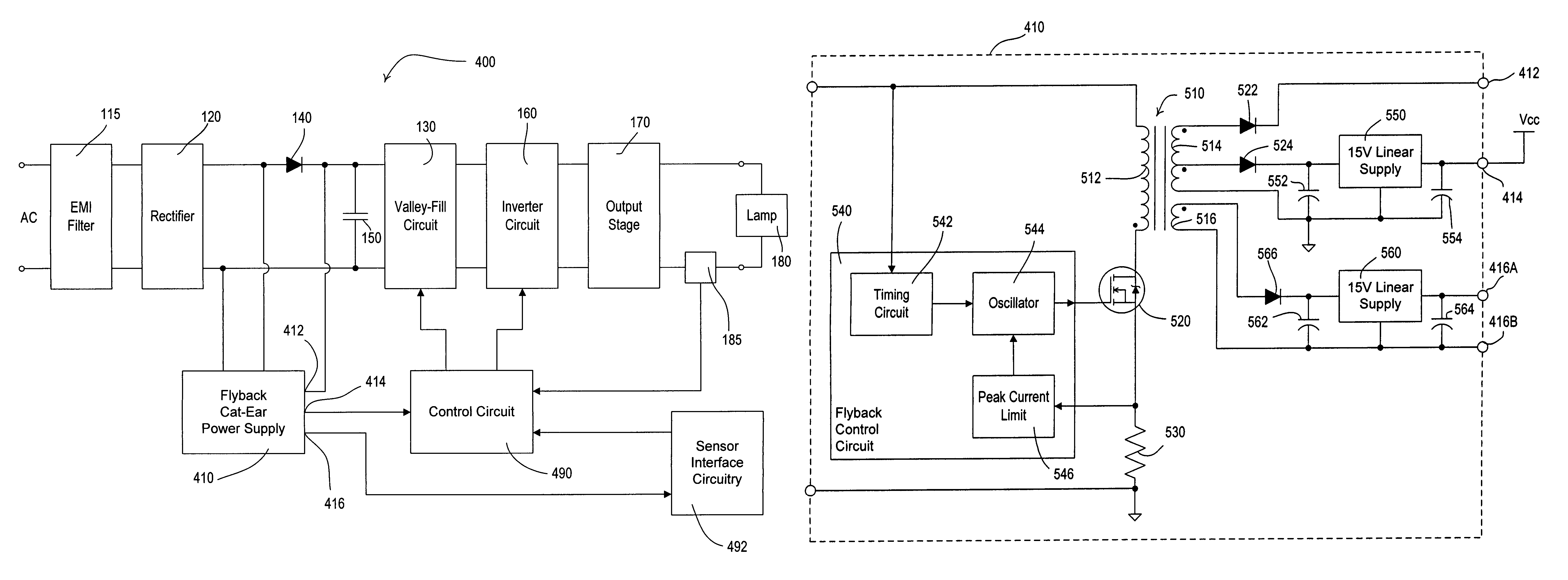
[0032]Referring to FIG. 4, there is shown a simplified schematic diagram of an electronic ballast 400 constructed in accordance with the invention. A flyback cat-ear power supply 410 is coupled to the output of the rectifier 120. A flyback converter can be defined as a buck-boost switch-mode power supply topology in which, during the first period of a switching cycle, the energy is stored in an inductance, and during the second period, this energy is transferred to a different w...


PUM


Abstract

An electronic ballast for driving a gas discharge lamp includes a rectifier to convert an AC mains input voltage to a rectified voltage, a valley-fill circuit for producing a DC bus voltage, an inverter for converting the DC bus voltage to a high-frequency AC voltage for driving the lamp, a control circuit for controlling the inverter, and a flyback cat-ear power supply for supplying current to the inverter when the rectified voltage is less than a predetermined level. The flyback cat-ear power supply also provides power to the control circuit. Preferably, the flyback cat-ear power supply draws current only when the inverter is not drawing current directly from the AC mains, so as to make the input current to the ballast substantially sinusoidal. The result is a ballast having substantially improved power factor and THD. Also, the ballast operates more efficiently because the flyback cat-ear ear power supply supplies excess energy not needed by the ballast control circuitry to the inverter to be used to drive the lamp.

Description

FIELD OF THE INVENTION[0001]The present invention relates to electronic ballasts and, more particularly, to electronic dimming ballasts for gas discharge lamps, such as fluorescent lamps.BACKGROUND OF THE INVENTION[0002]Electronic ballasts for fluorescent lamps typically include a “front end” and a “back end”. The front end typically includes a rectifier for changing alternating-current (AC) mains line voltage to a direct-current (DC) bus voltage and a filter circuit for filtering the DC bus voltage. The ballast back end typically includes a switching inverter for converting the DC bus voltage to a high-frequency AC voltage, and a resonant tank circuit having a relatively high output impedance for coupling the high-frequency AC voltage to the lamp electrodes.[0003]The front end of electronic ballasts also often include a boost converter, which is an active circuit for boosting the magnitude of the DC bus voltage above peak of line voltage, and for improving the total harmonic distor...

Claims


Application Information

Patent Timeline
Patent Type & Authority Patents(United States)
IPC IPC(8): H05B37/02G05F1/00
CPCH05B41/282Y02B20/183Y02B20/00
Inventor TAIPALE, MARK S.CHITTA, VENKATESHVESKOVIC, DRAGAN
Owner LUTRON TECH CO LLC
Why Eureka
Try Eureka