Subcutaneously implantable access port

a technology of access port and subcutaneous implant, which is applied in the field of implantable chambers to achieve the effect of reducing traumatism

Inactive Publication Date: 2008-11-04
B BRAUN MEDICAL
View PDF11 Cites 102 Cited by
  • Summary
  • Abstract
  • Description
  • Claims
  • Application Information

AI Technical Summary

Benefits of technology

[0011]The invention enables those problems to be solved by a combination of a profiled shape, which makes it difficult for the chamber to rotate on itself, and an

Problems solved by technology

Such a chamber poses the following problems.
The chamber constitutes a foreign body which causes some discomfort

Method used


Image

  • Subcutaneously implantable access port
  • Subcutaneously implantable access port
  • Subcutaneously implantable access port

Examples


Embodiment Construction

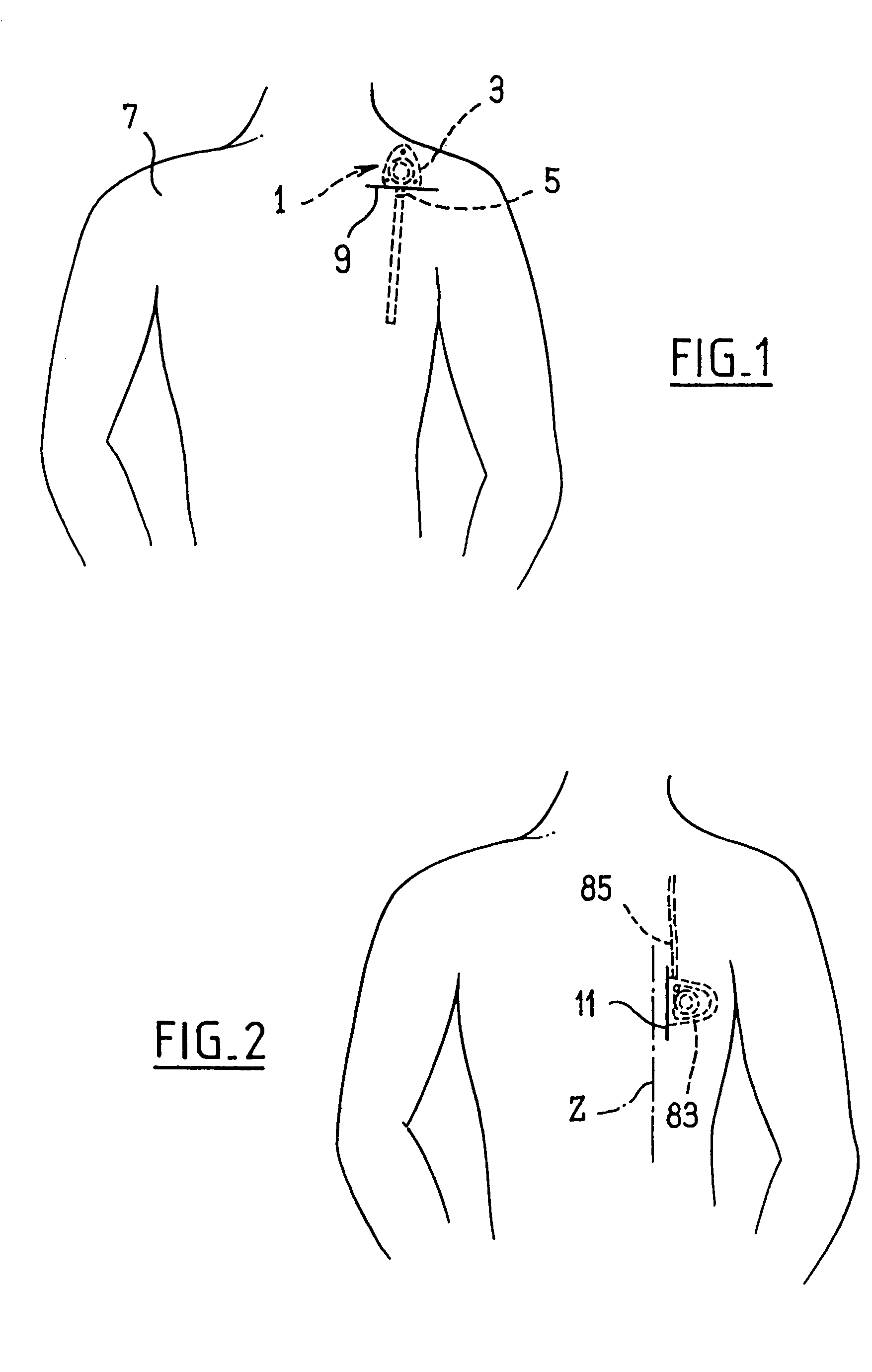
[0035]FIG. 1 illustrates the implantation of a traditional medicament infusion chamber 1, which is implanted subcutaneously, in the body 7 of a patient, by way of a horizontal incision. The chamber comprises a body 3 having a medicament reservoir. A diffusion (or sampling) duct 5 extends radially out of the body 3. The duct 5 is substantially perpendicular to the body in the vicinity of the horizontal incision 9 which has been made at least in the dermis of the body 7 in order to implant the chamber subcutaneously.

[0036]FIG. 2 illustrates the implantation of a medicament infusion chamber, which is implanted subcutaneously, in the body of a patient, by way of an incision 11 having a vertical direction Z. The chamber comprises a diffusion (or sampling) duct 85 which extends tangentially out of the body. The duct 85 is substantially parallel with the incision 11 which has been made at least in the dermis of the body in order to implant the chamber subcutaneously.

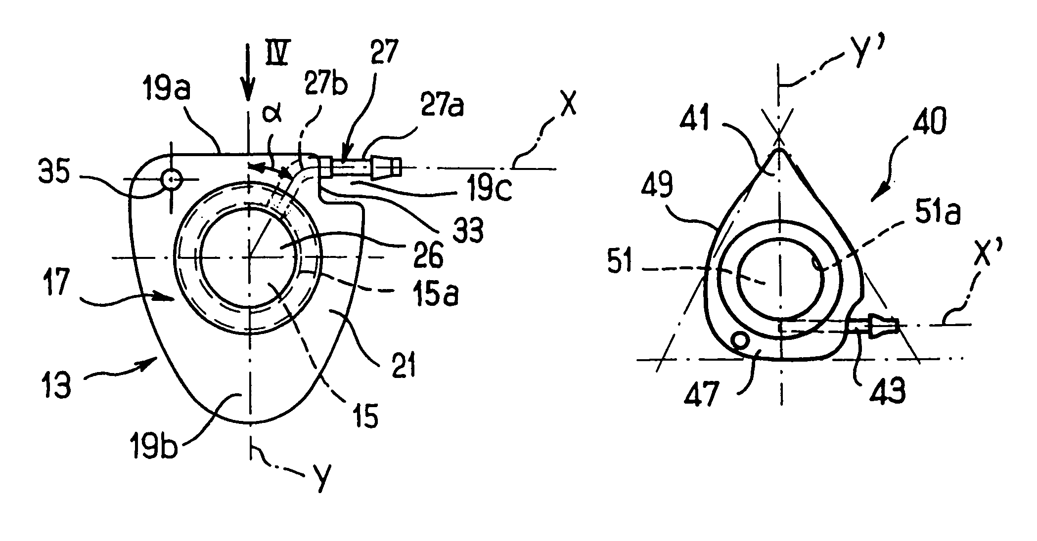
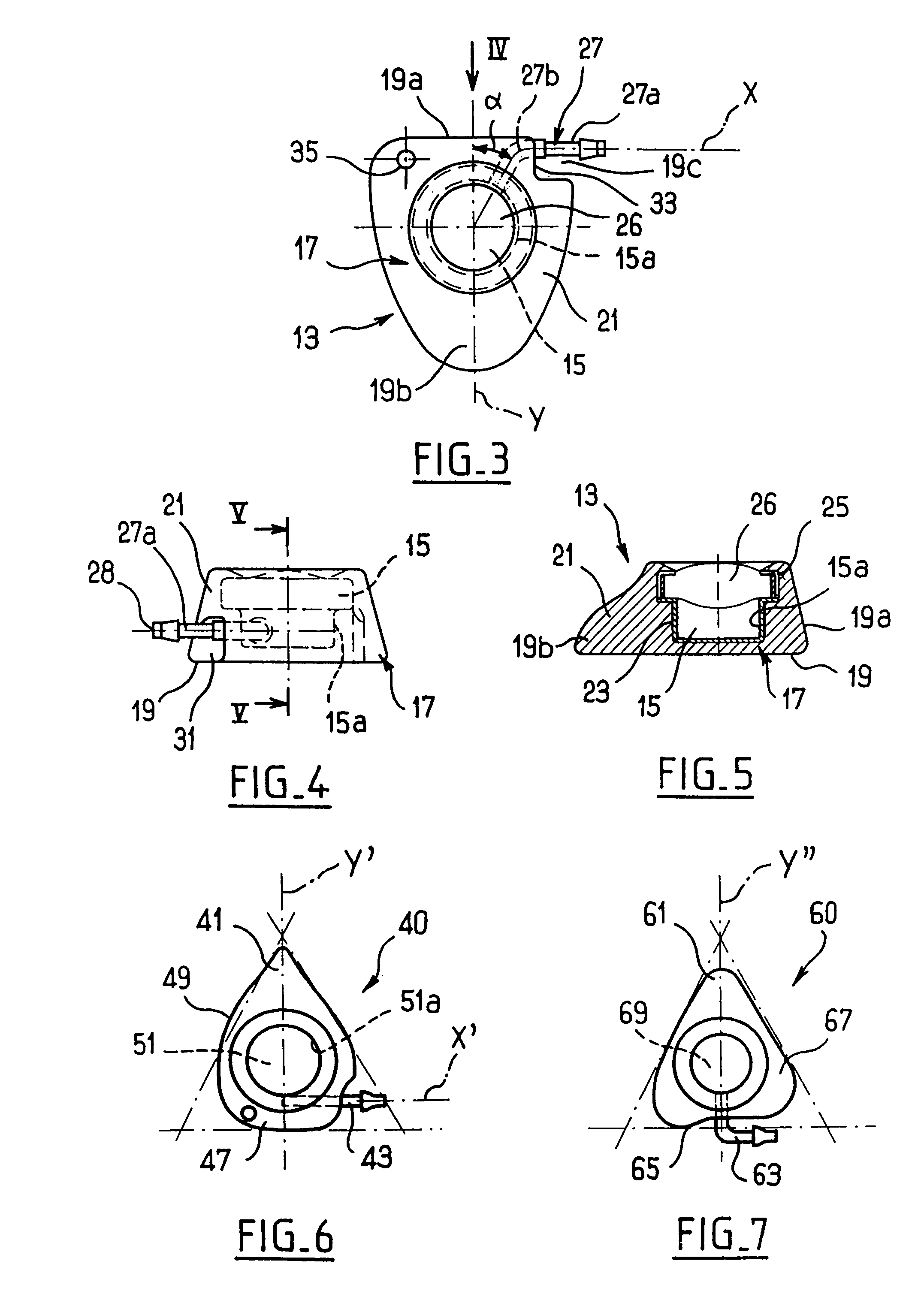
[0037]In FIGS. 3 to 5, ...


PUM


Abstract

A chamber for the infusion of a medicament. The chamber includes a reservoir, an outer casing having a base wall and a lateral wall, a region for access to the reservoir, and a duct for the diffusion of the medicament. A contour of the base wall is substantially triangular. The casing has a shape tapered in a first direction, and a terminal portion of the diffusion duct extends tranversely, and preferably perpendicularly, to the direction of tapering.

Description

BACKGROUND OF THE INVENTION[0001]The invention relates to an implantable chamber for the infusion of a medicament, which chamber is to be implanted subcutaneously by way of an incision in a body.[0002]Such chambers are already known; they comprise a medicament reservoir, a region for access to the reservoir, which region is accessible from outside the body and which is to enable the medicament reservoir to be filled, and a diffusion duct connected to the reservoir and extending outside the latter.[0003]Such chambers may also be used in the opposite manner, that is to say, for taking a sample of body fluid (blood in particular), the fluid collecting in the chamber from which it can be removed. Such chambers also fall within the ambit of the invention but the invention will be described hereinafter purely with reference to a chamber for the infusion of a medicament without limiting the scope of the invention to infusion chambers only.[0004]The chamber is to be implanted beneath the sk...

Claims


Application Information

Patent Timeline
IPC IPC(8): A61M31/00A61M39/02A61M37/00
CPCA61M39/0208A61M2039/0226A61M2039/0232
Inventor BUNODIERE, MICHELNADAL, GUY
Owner B BRAUN MEDICAL
Why Eureka
Try Eureka