Turbine blade cooling system

a cooling system and turbine blade technology, applied in machines/engines, mechanical equipment, liquid fuel engines, etc., can solve problems such as pressure delivery of cooling air to blade roots

Inactive Publication Date: 2008-12-02
ROLLS ROYCE PLC
View PDF15 Cites 21 Cited by
  • Summary
  • Abstract
  • Description
  • Claims
  • Application Information

AI Technical Summary

Problems solved by technology

However, such known systems suffer from the disadvantage of delivering the cooling air to ...

Method used


Image

  • Turbine blade cooling system
  • Turbine blade cooling system
  • Turbine blade cooling system

Examples


Embodiment Construction

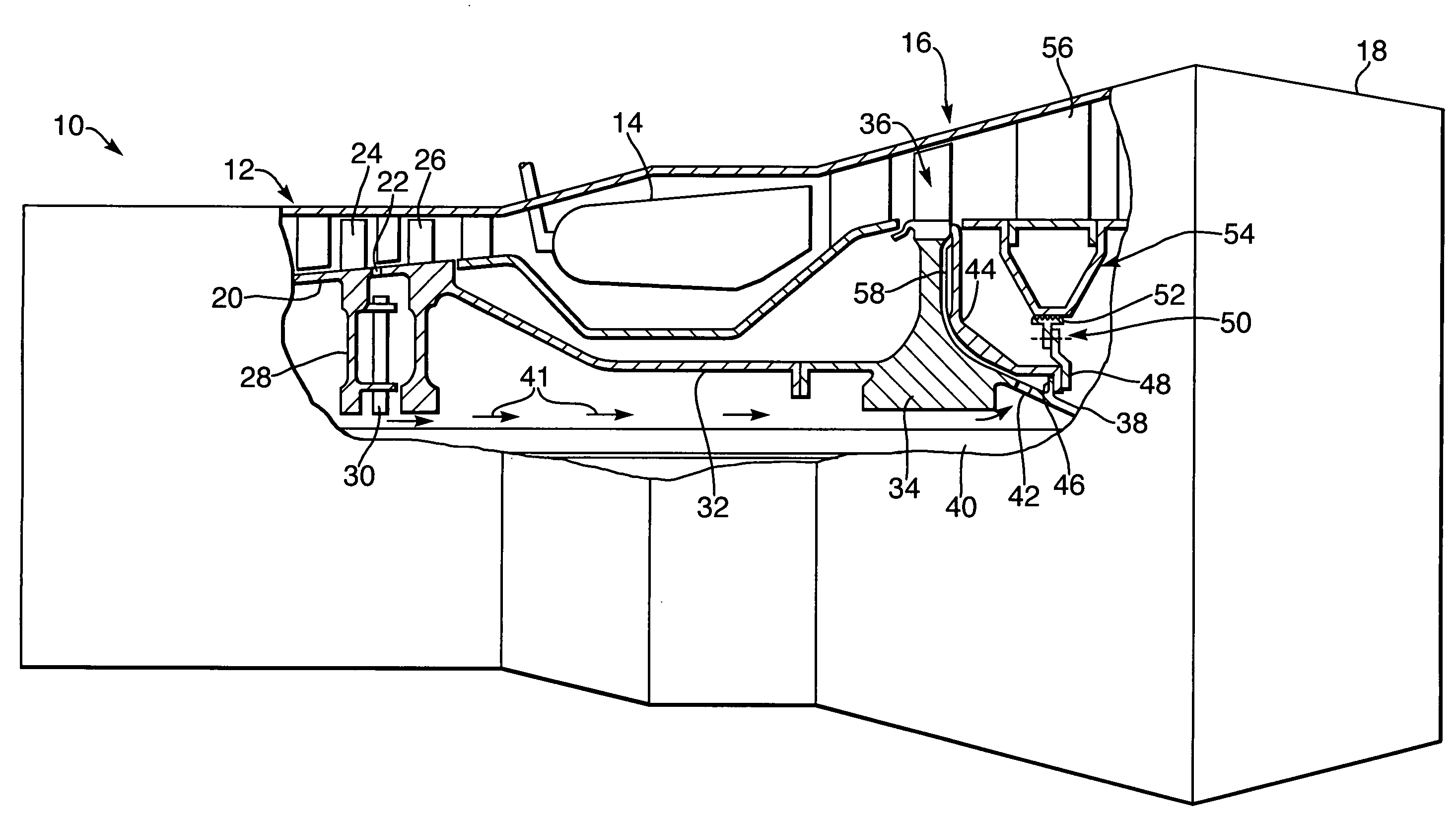
[0009]Referring to FIG. 1. A gas turbine engine 10 has a multi stage compressor 12, combustion equipment 14, a turbine section 16 and an exhaust nozzle 18. The inner annulus wall 20 of compressor 12 has a number of equiangularly spaced bleed holes 22 therethrough, only one of which holes is shown. In the present example, bleed holes 22 are positioned between the penultimate and ultimate stages of compressor blades 24 and 26.

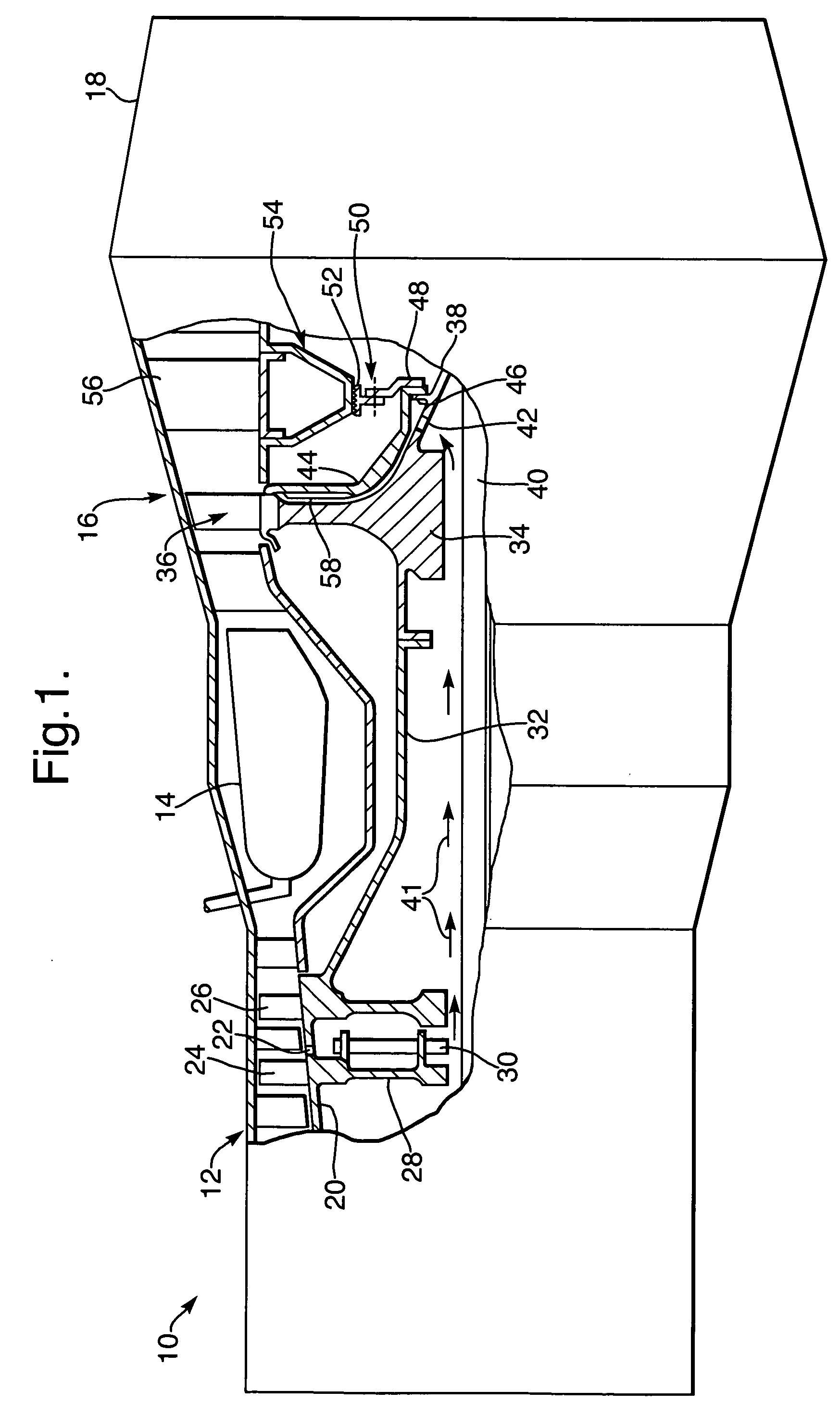
[0010]The stage of compressor blades 24 is carried on a disk 28, which also supports a radial turbine 30 for co-rotation therewith, during operation of gas turbine engine 10. Compressor 12 is connected via an annular cross-section shaft 32 to a disk 34 that carried turbine stage 36 for rotation thereby, during the said operation of gas turbine engine 10. An annular cross-section stub shaft 38 extends from the downstream side (with respect to the direction of gas flow through engine 10) of disk 34, and a bearing (not shown) maintains that stub shaft 38 in axial sp...


PUM


Abstract

Efficient cooling of a stage of gas turbine engine turbine blades (36) is achieved by first reducing the pressure of the cooling air after it has been bled from the annulus of the compressor (12) by passing it through a diffuser (30), to a pressure magnitude lower than is required at entry to the turbine blades, then re-pressurizing the bled air up to the required entry pressure, by passing it through a radial compressor defined by a cowl (44) positioned in close spaced, co-rotational relationship with the downstream face of the associated turbine disk (34).

Description

FIELD OF THE INVENTION[0001]The present invention relates to the cooling of turbine blades in a gas turbine engine. In particular, the present invention relates to a turbine blade cooling system wherein air bled from a compressor of an associated gas turbine engine, is passed to a stage of turbine blades carried on a rotary disk.BACKGROUND OF INVENTION[0002]It is known, to achieve turbine blade cooling by bled compressor air, which air is passed to the respective blade roots via holes in the rim of the associated turbine disk. However, such known systems suffer from the disadvantage of delivering the cooling air to the blades roots at pressures which are often not appropriate to the blades cooling requirements. Therefore, the present invention seeks to provide an improved turbine blade cooling system.SUMMARY OF THE INVENTION[0003]According to the present invention, a turbine blade cooling system comprises a compressor having a stage of compressor blades and compressed air bleed mean...

Claims


Application Information

Patent Timeline
IPC IPC(8): F03B11/00F01D5/08F01D15/08
CPCF01D5/082F01D5/087F01D15/08
Inventor DAILEY, GEOFFREY MSNOWSILL, GUY D
Owner ROLLS ROYCE PLC
Why Eureka
Try Eureka