Digital/analog TV receiver

a digital/analog tv receiver technology, applied in the field of digital/analog tv receivers, can solve the problems of increasing and achieve the effect of minimizing the overall duration of the full-range scanning process

Inactive Publication Date: 2008-12-23
FUNAI ELECTRIC CO LTD
View PDF5 Cites 5 Cited by
  • Summary
  • Abstract
  • Description
  • Claims
  • Application Information

AI Technical Summary

Benefits of technology

[0009]The present invention has been developed for achieving the above requirement and its object is to provide a digital / analog TV receiver arranged for carrying out the process of full-range scanning at a short length of time while capable of receiving both a ground wave and a cable wave of the broadcasting signal and both an analog form and a digital form of the ground wave signal.
[0011]According to the present invention, the process of full-range scanning involves attempting to receive a digital broadcasting signal, automatically examining from the result of the receipt whether the broadcasting signal is received from a ground wave transmission route or a cable wave transmission route, and automatically specifying the channel of the broadcasting signal received from the transmission route. The channel of the broadcasting signal is then registered and stored as a receivable channel in the channel map. As the transmission route from which the broadcasting signal is received is determined from the receipt of the digital signal in the ground wave signals, the action of determining the transmission route and specifying the channel of the broadcasting signal can efficiently be carried out thus minimizing the overall duration of the full-range scanning process.

Problems solved by technology

Accordingly, the step of specifying the transmission route of the broadcasting signal will consume a considerable length of time thus increasing the overall duration of the full-range scanning process.

Method used


Image

  • Digital/analog TV receiver
  • Digital/analog TV receiver
  • Digital/analog TV receiver

Examples


first embodiment

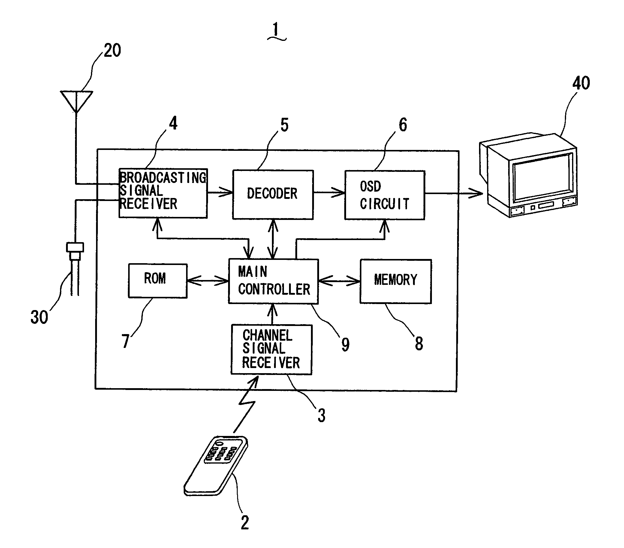
[0022]Some embodiments of the present invention will be described referring to the relevant drawings. FIG. 1 is an electrical block diagram of a digital / analog TV receiver showing the present invention. The digital / analog TV receiver 1 is connected to an antenna 20 for intercepting a television signal of ground wave, a cable 30 for receiving a television signal of cable wave, and a display 40 for displaying images of the television signals.

[0023]The TV receiver 1 is provided for receiving both digital and analog forms of the television signal via the antenna 20 from a broadcasting service station or an analog form of the cable wave television signal via the cable 30 and reproducing images of the television signals on the display 40. The TV receiver 1 has a full-range scanning function for examining whether the television signal is received from a ground wave transmission route or a cable wave transmission route and automatically determining a range of broadcast channels which can be...

second embodiment

[0044]Another digital / analog TV receiver according to the present invention will now be described. The process of full-range scanning in this embodiment can eliminate the step of examining the channel of a ground wave broadcasting signal of an analog form determined from the VCT data in the ground wave broadcasting signal of a digital form at the digital ground wave broadcasting signal channel examining step throughout the full range of frequencies. The other arrangement is identical to that of the previous embodiment.

[0045]The step of examining the channel of the ground wave broadcasting signal of an analog form throughout the full range of frequencies in the full-range scanning will be described referring to a flowchart of FIG. 8. The process starts with the main controller 9 identifying the channel as n=2 (Step #31) and examining whether or not the ground wave broadcasting signal of an analog form over the channel 2 has been found from the VCT data in the ground wave broadcasting...

third embodiment

[0048]A further digital / analog TV receiver according to the present invention will now be described. The process of full-range scanning in this embodiment can eliminate the step of examining the channel of a ground wave broadcasting signal of an analog form specified at the digital ground wave broadcasting signal channel examining step throughout the full range of frequencies. It can also eliminate the step of examining the channel of a ground wave broadcasting signal of an analog form determined from the VCT data in the ground wave broadcasting signal of a digital form at the digital ground wave broadcasting signal channel examining step. The other arrangement is identical to that of the previous embodiment.

[0049]The step of examining the channel of the ground wave broadcasting signal of an analog form throughout the full range of frequencies in the full-range scanning will be described referring to a flowchart of FIG. 9. The procedure starts with the main controller 9 identifying ...


PUM


Abstract

A digital / analog TV receiver is provided comprising a broadcasting signal receiver for receiving broadcasting signals of both ground wave and cable wave, a main controller which carries out the process of full-range scanning including a transmission route examining step of automatically specifying the transmission route of a broadcasting signal and a channel examining step of automatically specifying the channel of the broadcasting signal received from the transmission route, and a memory for holding a channel map where the channel of each broadcasting signal is stored. The main controller can carry out the transmission route examining step to check the receipt of the ground wave broadcasting signal of a digital form by the broadcasting signal receiver and automatically examine from the result of the checking whether the broadcasting signal is received from the ground wave transmission route or the cable wave transmission route. Also, the main controller can check the receipt of the broadcasting signal from the transmission route by the broadcasting signal receiver and automatically specify from the result of the checking the channel of the broadcasting signal received from the transmission route. The channel of the broadcasting signal is then stored into the channel map of the memory by the main controller.

Description

BACKGROUND OF THE INVENTION[0001]1. Field of the Invention[0002]The present invention relates to a digital / analog TV receiver which has a full-range scanning function for automatically identifying the transmission route of a broadcasting signal and automatically specifying the channel of the broadcasting signal as a receivable channel.[0003]2. Description of the Related Art[0004]The transmission route of television broadcasting signals is commonly classified into ground wave route and cable wave route. There are some TV receivers which can receive broadcasting signals from both the ground wave transmission route and the cable wave transmission route. When the frequency is different between the ground wave signal and the cable wave signal, the apparatus itself has to identify the transmission route of the broadcasting signal. Hence, a type of TV receiver is known which has a full-range scanning function for detecting the broadcasting signal received from a station, automatically iden...

Claims


Application Information

Patent Timeline
Patent Type & Authority Patents(United States)
IPC IPC(8): H04N5/50H03J7/18H04N5/44H04N5/46
CPCH04N5/4401H04N5/46H04N21/4383H04N21/4345H04N21/42638H04N5/50H04N21/426
Inventor ISHIHARA, KAZUHIDEKATAYAMA, TAKAHIRO
Owner FUNAI ELECTRIC CO LTD
Why Eureka
Try Eureka