Apparatus for and method of erasing residual radiation image

a residual radiation and image technology, applied in the field of apparatus for and erasing residual radiation images, can solve the problems of wasting electric energy, wasting erasing energy, waste of electric energy, etc., and achieve the effect of erasing the residual radiation image at the minimum level and ensuring the effect of erasing energy

Inactive Publication Date: 2009-03-17
FUJIFILM CORP +1
View PDF21 Cites 3 Cited by
  • Summary
  • Abstract
  • Description
  • Claims
  • Application Information

AI Technical Summary

Benefits of technology

[0011]It is a general object of the present invention to provide an apparatus for and a method of efficiently and reliably erasing a residual radiation image from a stimulable phosphor panel with a required minimum level of erasing energy.
[0012]A principal object of the present invention is to provide an apparatus for and a method of efficiently erasing radiation energy remaining in a stimulable phosphor panel by applying erasing light having appropriate erasing energy depending on the residual radiation energy.
[0013]Another principal object of the present invention is to provide an apparatus for and a method of efficiently erasing a residual radiation image from a stimulable phosphor panel by applying erasing light to an area of the stimulable phosphor panel which depends on the size of the stimulable phosphor panel.

Problems solved by technology

If erasing light exclusive of ultraviolet radiation is used to erase the remaining radiation image from the stimulable phosphor panel, then electrons trapped in a deep layer where they cannot be removed by visible erasing light tend to remain unremoved.
As a result, the erasing process tends to result in a wasteful consumption of electric energy.
If the level of erasing energy is established based on the maximum stimulable phosphor panel size regardless of different stimulable phosphor panel sizes that are actually used, then some erasing energy is also wasted.

Method used


Image

  • Apparatus for and method of erasing residual radiation image
  • Apparatus for and method of erasing residual radiation image
  • Apparatus for and method of erasing residual radiation image

Examples


Embodiment Construction

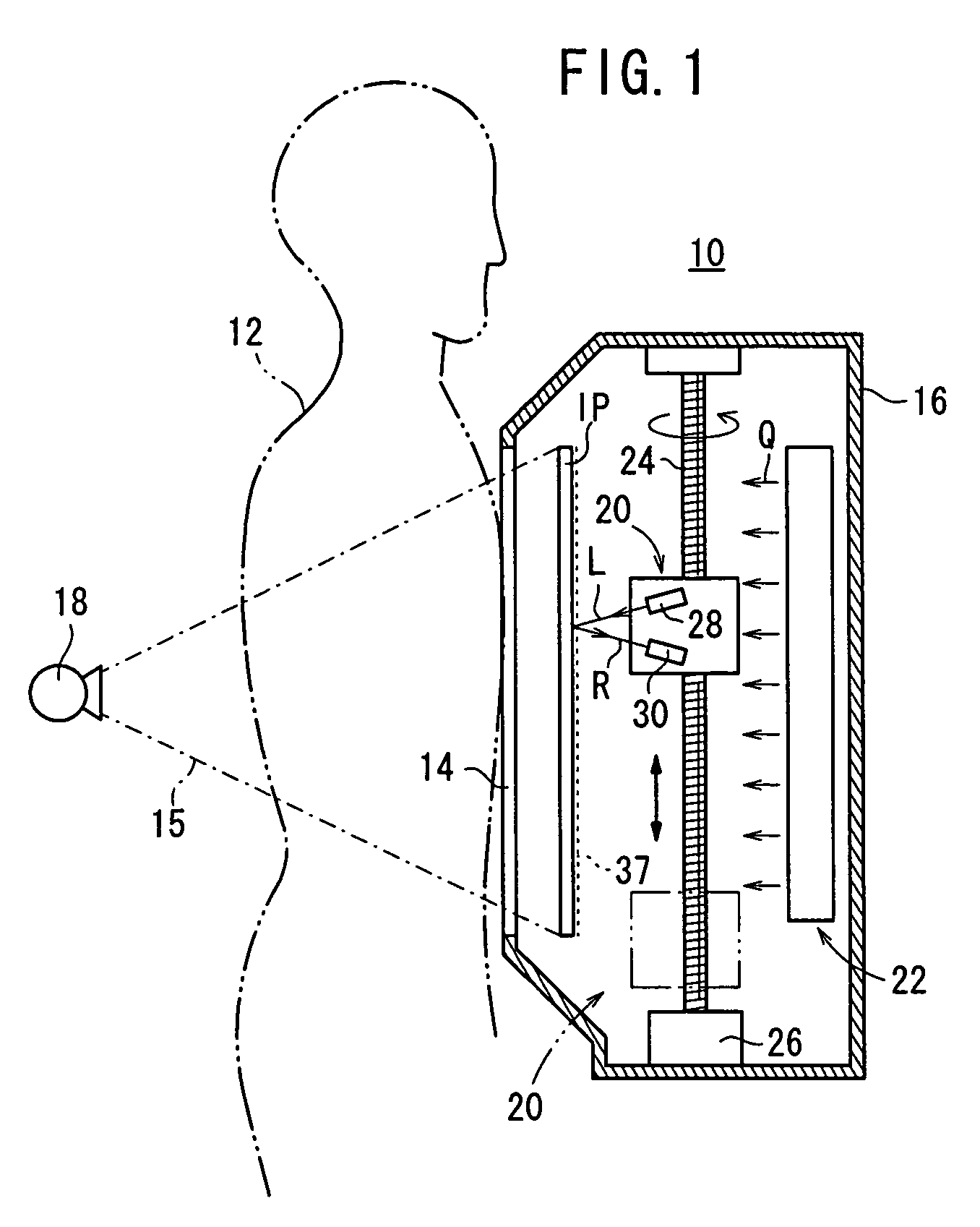
[0023]FIG. 1 shows in vertical cross section an upright imaging system 10 incorporating therein an apparatus for and a method of erasing a residual radiation image according to the present invention.

[0024]As shown in FIG. 1, the upright imaging system 10 has, in addition to a function to record a radiation image of a subject 12 such as a human body or the like on a stimulable phosphor panel IP, a function to read a radiation image from a stimulable phosphor panel IP, and a function to erase a residual radiation image which remains in a stimulable phosphor panel IP from which a recorded radiation image has been read.

[0025]The stimulable phosphor panel IP may comprise a hard panel having a columnar stimulable phosphor layer vapor-deposited on a support board of a hard material such as glass or the like. The columnar stimulable phosphor layer may be formed by any of various processes including a vacuum evaporation process in which a stimulable phosphor is heated and evaporated in a vac...


PUM

PropertyMeasurementUnit
wavelength rangeaaaaaaaaaa
radiation energyaaaaaaaaaa
erasing energyaaaaaaaaaa

Abstract

A stored quantity calculator calculates the quantity of radiation energy stored in each of divided areas of a stimulable phosphor panel. Erasing energy set to a level depending on the calculated quantity of radiation energy stored in each of the areas is applied from an erasing unit to the stimulable phosphor panel. Therefore, a residual radiation image remaining in the stimulable phosphor panel is efficiently erased with a required minimum level of erasing energy.

Description

BACKGROUND OF THE INVENTION[0001]1. Field of the Invention[0002]The present invention relates to an apparatus for and a method of erasing a residual radiation image from a stimulable phosphor panel by applying erasing light to the stimulable phosphor panel after a radiation image has been read from the stimulable phosphor panel by applying stimulating light to the stimulable phosphor panel.[0003]2. Description of the Related Art[0004]There has heretofore been known a stimulable phosphor which, when exposed to radiation (X-rays, α-rays, β-rays, γ-rays, electron beams, ultraviolet radiation, or the like), stores part of the energy of the radiation, and, when subsequently exposed to stimulating rays such as visible light, emits light in proportion to the stored energy of the radiation.[0005]A radiation image information recording and reproducing system, which has been developed in the art, temporarily records a radiation image of a subject such as a human body on a stimulable phosphor ...

Claims


Application Information

Patent Timeline
Patent Type & Authority Patents(United States)
IPC IPC(8): G01N23/02
CPCA61B6/00A61B6/4216G01T1/2016
Inventor SUZUKI, KIYOTAKA
Owner FUJIFILM CORP
Why Eureka
Try Eureka