Jack bolt activated tensile strength test machine

a tensile strength and testing machine technology, applied in the direction of instruments, measurement devices, scientific instruments, etc., can solve the problems of expensive purchase and reliance, devices and methods, and prior art devices and methods are not without shortcomings, so as to achieve the effect of quick and easy adaptation

Inactive Publication Date: 2009-04-07
MJT HLDG
View PDF9 Cites 20 Cited by
  • Summary
  • Abstract
  • Description
  • Claims
  • Application Information

AI Technical Summary

Benefits of technology

[0011]The present invention has been developed in response to the current state of the art, and in particular, in response to these and other problems and needs that have not been fully or completely solved by currently available tensile strength testing machines and methods. Thus, it is an overall object of the present invention to effectively resolve at least the problems and shortcomings identified herein. In particular, it is an object of the present invention to provide a tensile testing machine wherein the load which is generated for the purpose of tensioning the test specimen is applied through the use of hand operated wrenches applied to jack bolts that are arrayed in a collar element generally around an arbor element. It is also an object of the present invention to provide a tensile strength testing machine that is particularly adapted to proof testing manufactured articles. Finally, it is an object of the present invention to provide a tensile strength testing machine that is particularly adapted to quickly, easily, and reliably proof testing manufactured articles in a manufacturing operation for purposes of quality control.

Problems solved by technology

The prior art devices and methods are not without their shortcomings.
A major shortcoming of typical prior art devices and methods is that they are expensive to purchase and rely, for example, on hydraulic activators, or the like, which require maintenance, repair, and some skill in their operation.
They are generally not quick enough or simple enough to use for purposes of proof testing manufactured articles in a manufacturing operation for purposes of quality control.
Previously proposed expedients tended to be unsuitable for use in a manufacturing environment, among other reasons, because of costs, complexity, maintenance cost, or slow cycle times.

Method used


Image

  • Jack bolt activated tensile strength test machine
  • Jack bolt activated tensile strength test machine
  • Jack bolt activated tensile strength test machine

Examples


Embodiment Construction

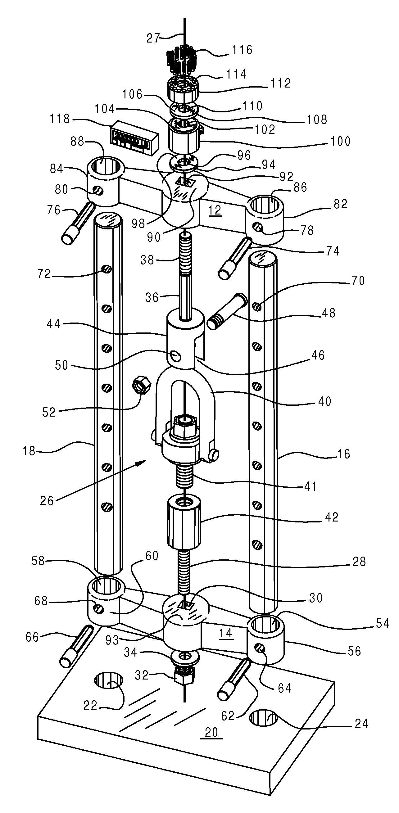
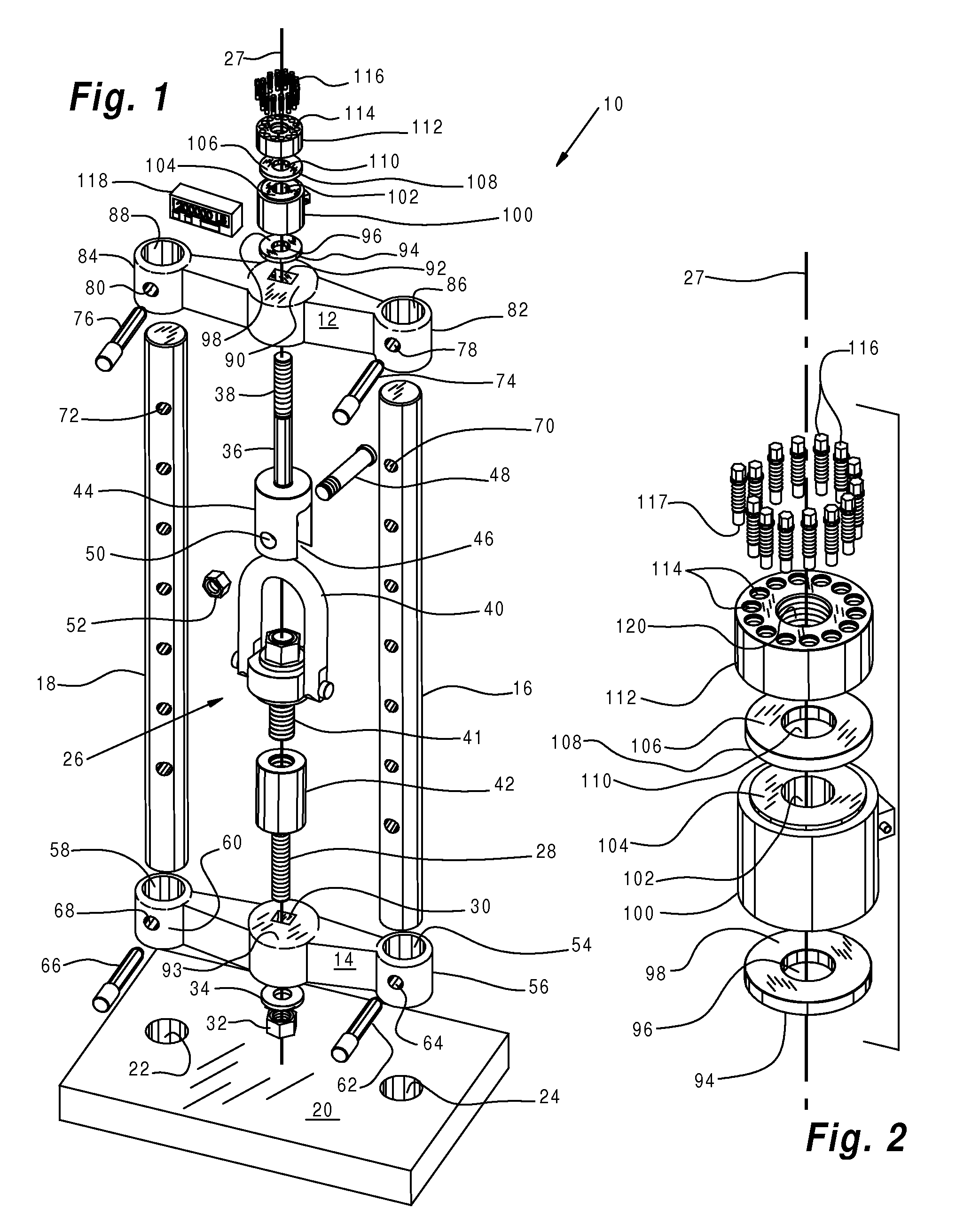
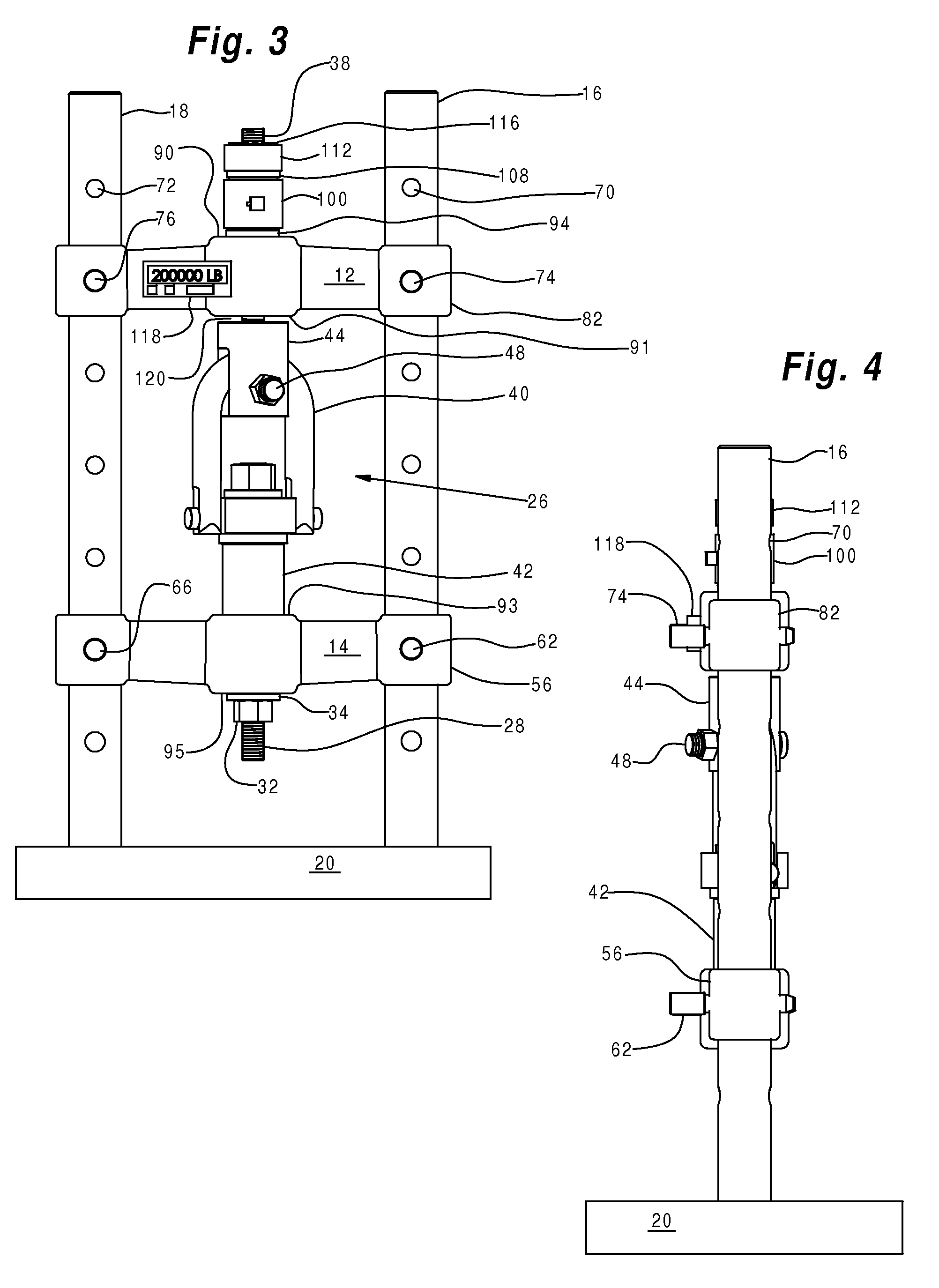
[0021]Referring now to the drawings wherein like reference numerals designate identical or corresponding parts throughout the several views. It is to be understood that the drawings are diagrammatic and schematic representations of various embodiments of the invention, and are not to be construed as limiting the invention in any way. The use of words and phrases herein with reference to specific embodiments is not intended to limit the meanings of such words and phrases to those specific embodiments. Words and phrases herein are intended to have their ordinary meanings, unless a specific definition is set forth at length herein.

[0022]Referring particularly to the drawings there is illustrated generally at 10, a tensile strength testing machine for imposing a tensile load on a test specimen mounted in a test zone indicated generally at 26. In the embodiment chosen for purposes of illustration, the illustrated test specimen is a swiveling hoist ring that includes a lifting loop 40 and...


PUM

PropertyMeasurementUnit
heightaaaaaaaaaa
heightaaaaaaaaaa
diameteraaaaaaaaaa

Abstract

A tensile strength testing machine comprises a frame assembly that defines a test zone. The frame assembly includes a frame member that has first and second opposed ends. The ends have inner sides that generally face one another across the test zone, and outer sides that are generally opposed to one another and the test zone. An arbor element is mounted for generally axial movement relative to the first end. The arbor element is slidably mounted in the first end. The arbor element projects inwardly into the test zone and outwardly from the outer side of the first end. The arbor element is adapted to being attached to a test specimen, which mounted in the test zone. A portion of the arbor element that projects outwardly from the outer side of the first end is generally surrounded by an array of jack bolts. The jack bolts are threadably mounted in a collar member that is substantially axially fixed relative to the arbor element. The jack bolts are positioned to bear generally against the outer side of the first end. Typically, at least a thrust collar, and, preferably, a load determining assembly are interposed between this outer side and the bearing ends of the jack bolts. Torquing down the jack bolts against the outer side of the first end places the arbor element in tension. This tensile load is applied to a test specimen mounted in the test zone, and the magnitude of the load is determined.

Description

RELATED APPLICATIONS[0001]This application claims the benefit of U.S. Provisional patent application Ser. No. 60 / 786,892, filed Mar. 29, 2006BACKGROUND OF THE INVENTION[0002]1. Field of the Invention[0003]The invention relates in general to methods and devices for mechanically testing the tensile strength of an article, and, more particularly, embodiments of the present invention relate to jack bolt activated tensile strength testing machines.[0004]2. Description of the Prior Art[0005]Tensile strength testing machines and methods have been widely used for many years for determining the mechanical tensile strengths of various articles. The prior art devices and methods are not without their shortcomings. A major shortcoming of typical prior art devices and methods is that they are expensive to purchase and rely, for example, on hydraulic activators, or the like, which require maintenance, repair, and some skill in their operation. They are generally not quick enough or simple enough ...

Claims


Application Information

Patent Timeline
Patent Type & Authority Patents(United States)
IPC IPC(8): G01N3/08
CPCG01N3/16G01N2203/0003G01N2203/0017G01N2203/0037G01N2203/0067
Inventor ALBA, TONY J.
Owner MJT HLDG
Why Eureka
Try Eureka