Test core clamp

Inactive Publication Date: 2006-04-04
GLYNN TIMOTHY DALE
View PDF16 Cites 7 Cited by
  • Summary
  • Abstract
  • Description
  • Claims
  • Application Information

AI Technical Summary

Benefits of technology

[0005]It is therefore an object of the present invention to provide a cl

Problems solved by technology

This is clearly a dangerous operation and has resulted in the accidental removal of more than a few

Method used


Image

  • Test core clamp
  • Test core clamp
  • Test core clamp

Examples


Embodiment Construction

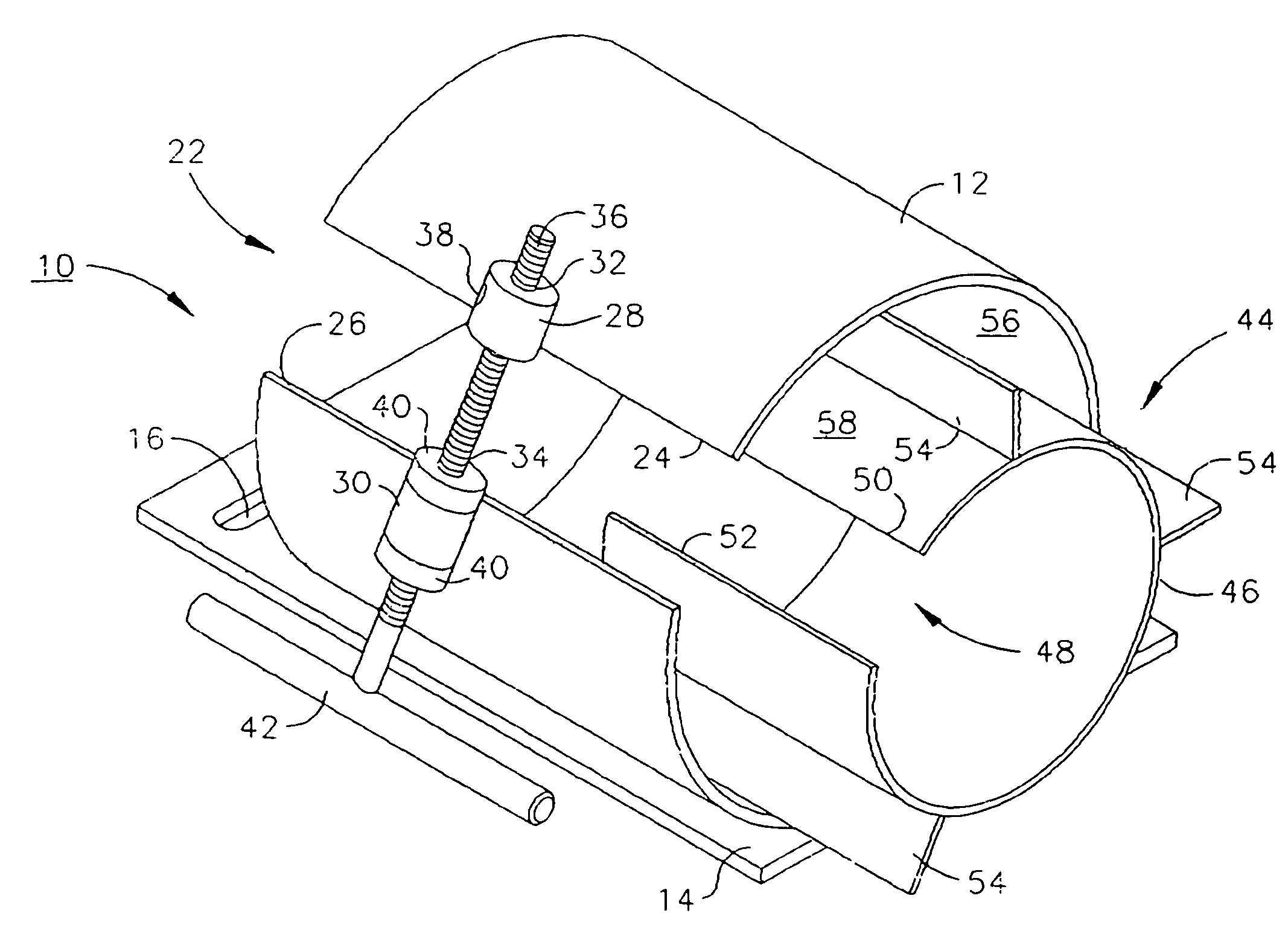
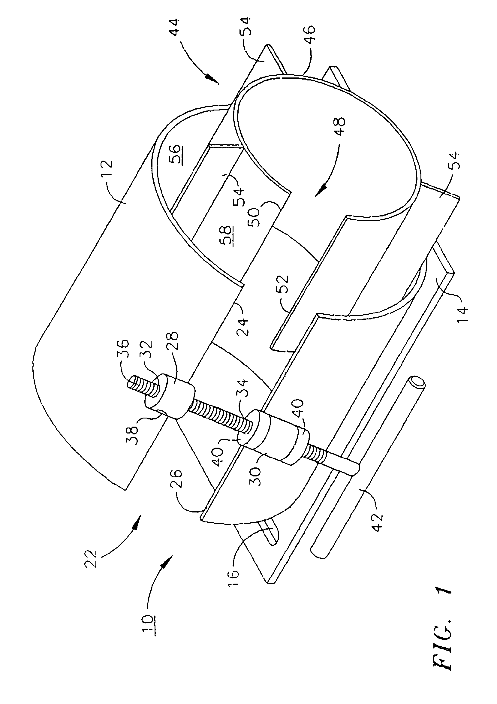
[0013]Referring now to FIG. 1, the test core clamping device of the present invention 10 comprises a first split tube 12 attached to a base 14 having mounting hole(s) 16 (only one is visible in the depiction of FIG. 1) therein for attachment of base 14 to a saw bed 18 by, for example, bolts 20 (shown in FIG. 5).

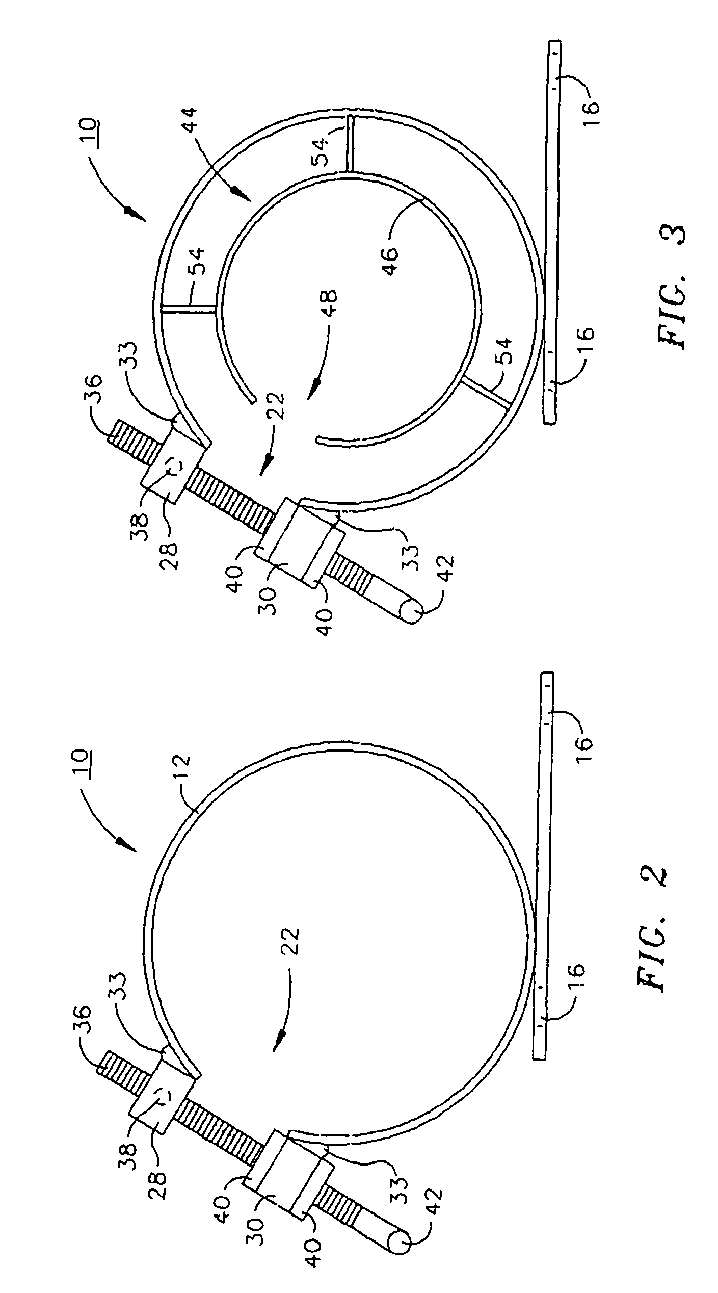
[0014]Split portion 22 is defined by opposing ends 24 and 26. Attached by welds 33 (see FIGS. 2 and 3) or other suitable means to first split tube 12 in the vicinity of each of opposing ends 24 and 26 are brackets 28 and 30. Bracket 28 has a threaded aperture 32 therein while bracket 30 has an aperture 34 that is sufficiently large as to permit passage of threaded bolt 36 therethrough without engagement. Bracket 28 is preferably equipped with a grease fitting 38 to permit greasing of the engaging threads of aperture 32 and threaded bolt 36 as devices of this type are commonly used and stored out of doors. In the embodiment depicted in the Figures, bracket 30 retains threaded ...


PUM


Abstract

A test core clamp comprising a first longitudinally split tube comprising a split portion having opposing ends and attached to a base, and a tightening device for moving the opposing ends towards each other. The tightening device comprises two brackets one affixed to each of the opposing ends and both having apertures therein. One of the bracket apertures is threaded to engage one end of a clamping bolt inserted through and rotating freely within the other bracket aperture such that rotation of the clamping bolt causes the opposing ends to close or open. According to a preferred embodiment, an insert comprising a second longitudinally split tube having a plurality of fins extending radially from its outer surface is slideably located inside of the first split tube with the fins frictionally engaging the inner surface of the first split tube such that closing and opening of the first split tube results in opening and closing of the second split tube.

Description

FIELD OF THE INVENTION[0001]The present invention relates to clamping devices and more particularly to clamping devices used in the clamping of test core samples for sawing or cutting.BACKGROUND OF THE INVENTION[0002]There are innumerable civil engineering, archeological and geological areas where so-called test core sampling is applied. Such sampling generally involves the extraction of a “core” i.e. a round sample drilled from or to a depth in an area to be studied. One such area of use of core samples is in the application of macadam or black top and concrete to highways, parking lots and the like. It is conventional practice for the “owner” of the surface to be finished, such as an individual state or the Federal Government to specify the density of application of such surfaces. In such cases, after macadam application and compacting, a “test core” or round sample is extracted from the applied surface and its density measured against the density specification. In such situations...

Claims


Application Information

Patent Timeline
IPC IPC(8): B66C1/42
CPCE21B25/005
Inventor GLYNN, TIMOTHY DALE
Owner GLYNN TIMOTHY DALE
Why Eureka
Try Eureka