
Airbag

a technology for airbags and occupants, applied in the field of airbags, can solve the problems of inability or very restricted extent, and achieve the effects of increasing time and cost, reducing manufacturing costs, and being very easy to manufacture and inexpensively

Active Publication Date: 2012-04-26
TRW AUTOMOTIVE GMBH
View PDF8 Cites 7 Cited by
  • Summary
  • Abstract
  • Description
  • Claims
  • Application Information

AI Technical Summary

Benefits of technology

[0007]The invention provides an airbag, especially a passenger front airbag, which can be manufactured very easily and inexpensively and which primarily excels by the fact that its design can be adapted very quickly to different interior contours. This adaptability is of great importance especially when it is attempted to optimize new vehicles, for completely new airbag designs considerably increase the expenditure on time and cost for optimizing the adjustment of the airbag to the interior.
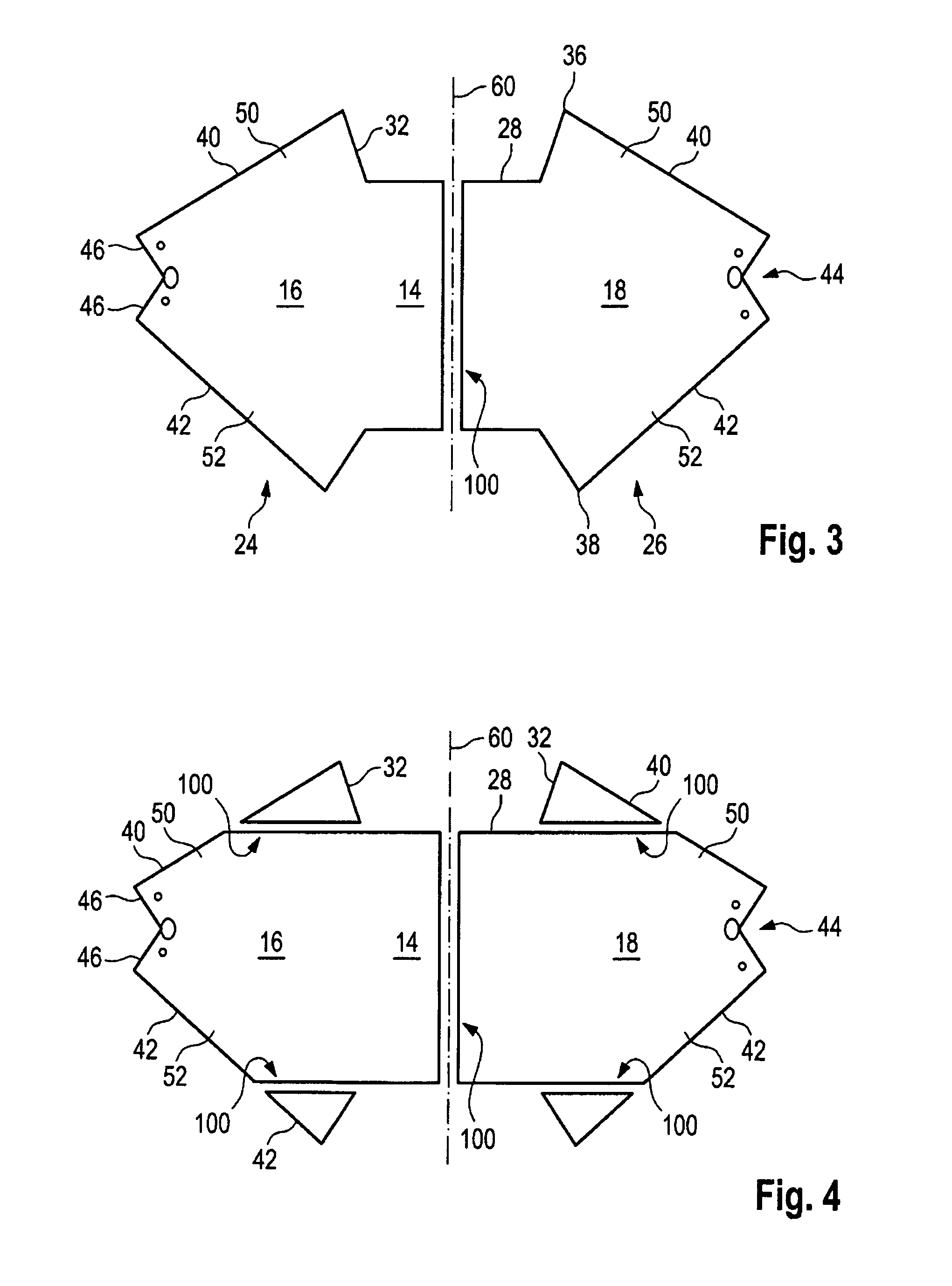
[0010]In contrast to this, the side portions of which the upper and lower walls of the airbag according to the invention are composed can be adapted very quickly and easily by quite simply designing the respective margins in a different way.
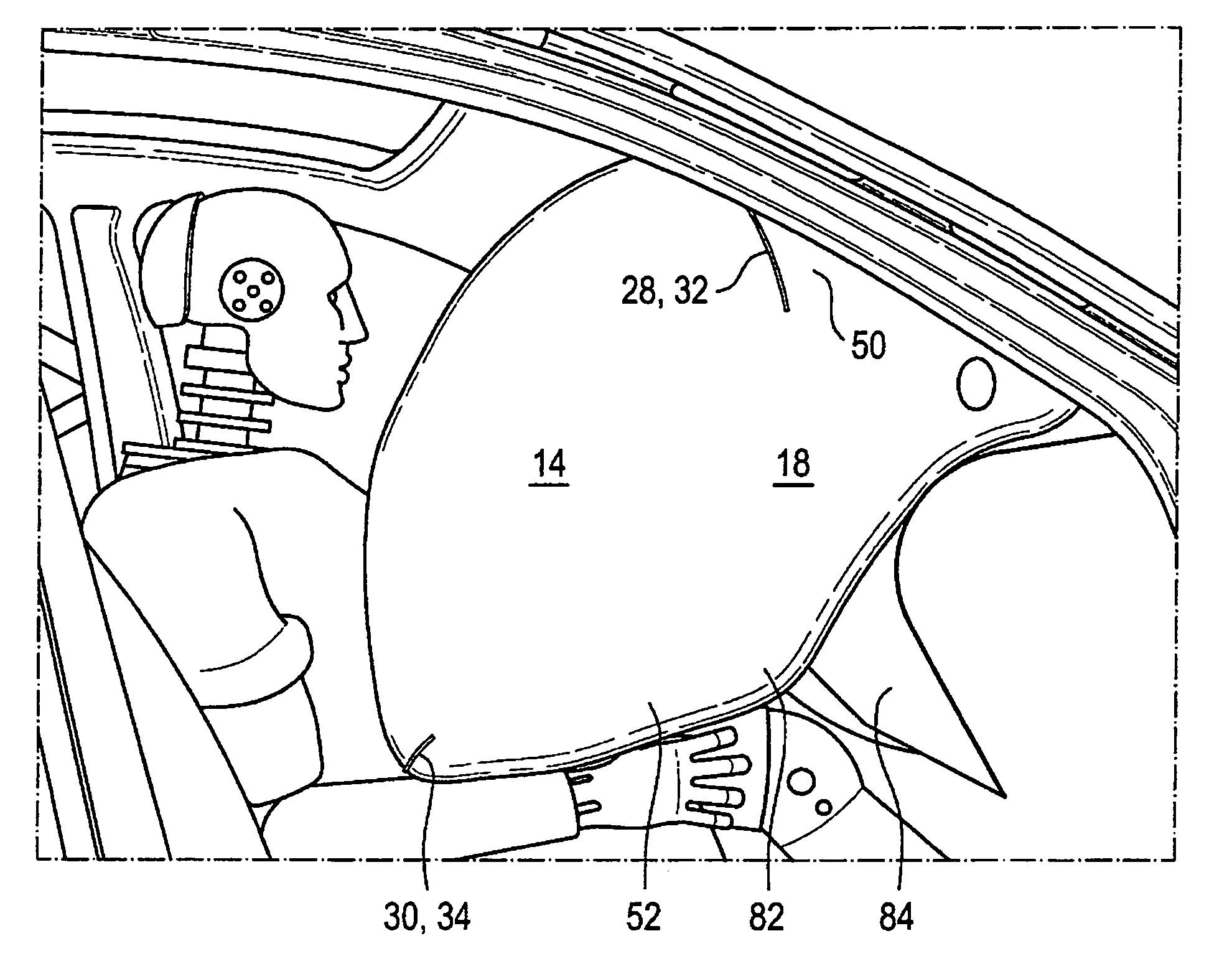
[0012]On the other hand, a different embodiment provides that the margins do not extend linearly. In this case the margins extend outwardly arched, for instance, so that a curvature is formed. Thus an outwardly directed bulge is imparted to the airbag at its upper and / or lower walls. This bulge makes it possible that the upper and / or lower walls does not extend linearly, viewed in the side view of the inflated airbag, but gets sort of a kink by which the airbag can adapt to the contour of the instrument panel. In this way the bulge becomes sort of a direct support surface at the instrument panel. The corresponding airbag volume reduces a hollow space between the thighs of the average occupant and the vertical portion of the instrument panel which in the case of previous airbags was hardly filled. This resulted in the fact that in the event of restraint during impact of the occupant onto the airbag this space was initially filled by the fact that the airbag was pressed into the same before it could be backed by the largely vertically extending portion of the instrument panel.
[0028]If the airbag according to the invention is composed of several parts, a reduced waste of cloth can be realized.

Problems solved by technology

If, however, the geometry of the upper and lower walls and thus the airbag shape is to be varied in these areas, this is not possible or possible to a very restricted extent only.

Method used


Image

  • Airbag
  • Airbag
  • Airbag

Examples


Embodiment Construction

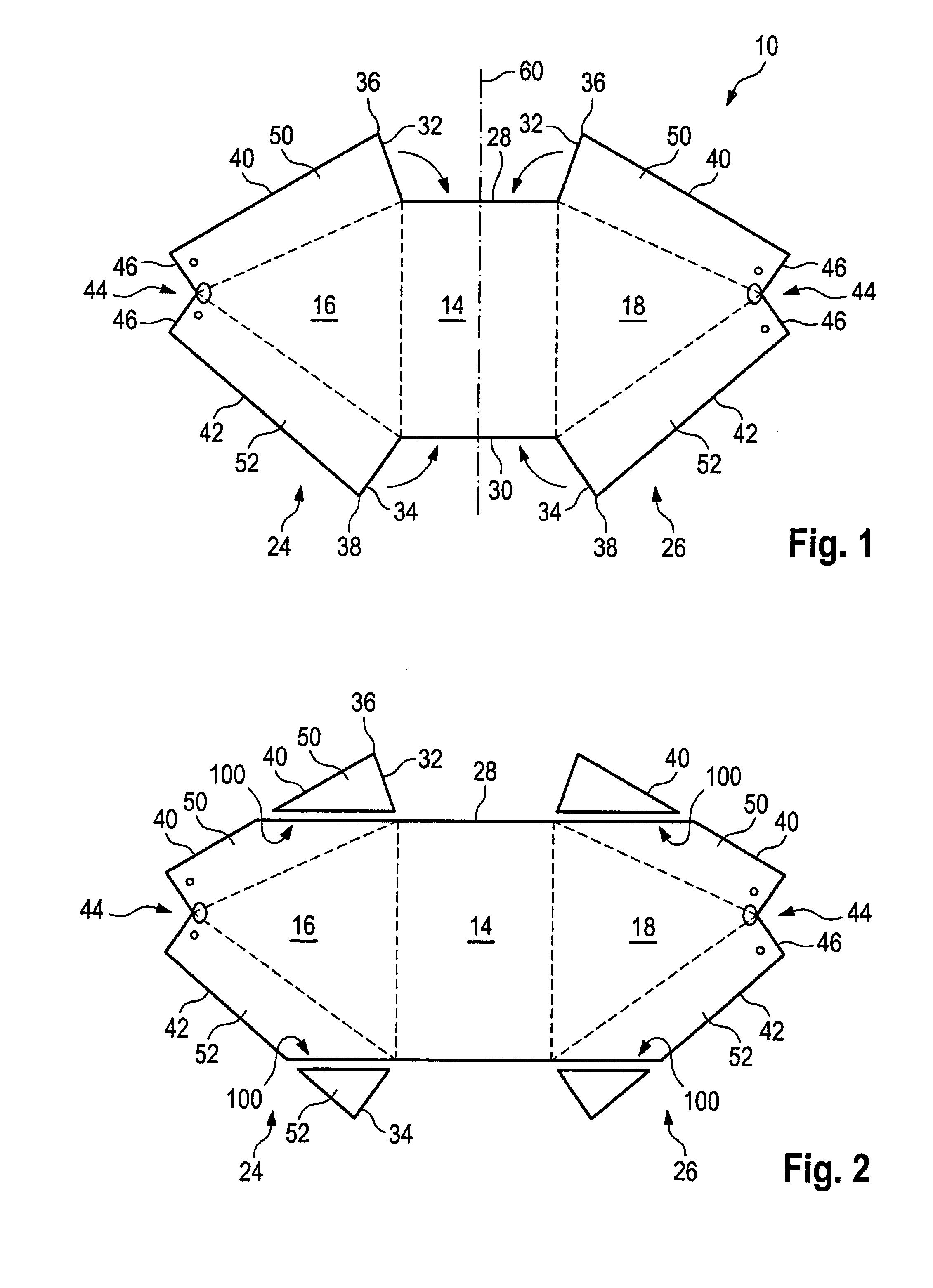
[0044]In FIG. 1 the cut of a so-called two-dimensional airbag for a passenger is illustrated, the airbag being accommodated in the instrument panel and being designed for a head-on impact.

[0045]In the present embodiment the airbag is formed of a single cloth part the margins of which are laid on top of each other and interconnected by simple folding, as will be described in detail hereinafter. In the FIGS. 12 and 13 the airbag according to FIG. 9 is represented which is slightly different from that of FIG. 1, wherein, for the purpose of illustration, first the airbag according to FIG. 13 is described so as to obtain the comprehension of the cloth portions and cloth parts.

[0046]The airbag 10 includes a rear injection orifice 12 as well as an opposite front wall 14 onto which the occupant impacts. Moreover, two opposed sidewalls 16, 18 which are converted into an upper wall 20 and a lower wall 22 are provided.

[0047]These aforementioned walls are formed by the one-piece cloth part acco...


PUM


Abstract

An airbag, especially a passenger airbag, comprises a rear injection orifice, a front wall (14) for the impact of the occupant as well as two opposed sidewalls (16,18) and an upper wall and a lower wall. Each of the upper and lower walls is split and consists of side portions (50, 52) which are juxtaposed and are connected to each other along opposite margins (40, 42).

Description

TECHNICAL FIELD[0001]The invention relates to an airbag, especially a passenger airbag, comprising a rear inflation orifice, a front wall for the impact of the occupant, two opposed sidewalls as well as an upper wall and a lower wall.BACKGROUND OF THE INVENTION[0002]In the case of airbags, depending on the interior dimensions and the contour of the adjacent surfaces (especially the instrument panel) airbags having different characteristics are employed. In the case of very plane surfaces and simple contours the so-called two-dimensional airbags adapted to be manufactured at lower cost are used. In the case of these airbags it is possible to manufacture the airbag of a one-piece cloth part which is then folded and sewed at the margins which are adjacent by folding. Those two-dimensional airbags are suited for rather simple contours, however, as mentioned already. What is important with the airbag is the fact that it can contact an adjacent vehicle part and can be backed by the same i...

Claims


Application Information

Patent Timeline
Patent Type & Authority Applications(United States)
IPC IPC(8): B60R21/16B60R21/231
CPCB60R21/231B60R2021/0048B60R2021/23571B60R2021/01238B60R2021/23533
Inventor ARANZULLA, DANIELEBURKHARDTSMAIER, MARTINWERNER, NICOPYS, TOMASZ
Owner TRW AUTOMOTIVE GMBH
Learn More