
System for Visually Depicting Fields of View of a Commercial Vehicle

a technology for visualizing and displaying commercial vehicles, which is applied in the field of visualizing fields of view of commercial vehicles, can solve the problems of increasing the burden on the vehicle driver to substantially simultaneously maintain all of the mirrors in view, affecting the safety of the vehicle driver, and reducing the safety of the vehicle. , to achieve the effect of increasing driving safety

Inactive Publication Date: 2017-12-28
MEKRA LANG GMBH & CO KG
View PDF16 Cites 7 Cited by
  • Summary
  • Abstract
  • Description
  • Claims
  • Application Information

AI Technical Summary

Benefits of technology

The patent describes a display device that allows drivers to easily monitor the area behind their vehicles while driving. The display is positioned upright and can be adjusted based on the driver's perspective. The display shows additional visual information from areas around the vehicle that may not be in the driver's traditional field of view. The display can have a single display unit that shows information from multiple fields of view, and image capture units are used to capture information for each field of view. The display units have a separate power supply, so they can be used even when the vehicle is stationary and the ignition is off. This improves safety and reduces the likelihood of accidents.

Problems solved by technology

However, in spite of the above-mentioned legally-prescribed mirrors and / or devices for indirect viewing, it is scarcely possible and / or very difficult for a vehicle driver to completely and sufficiently maintain in view at all times the areas around a commercial vehicle that are prone to accidents.
Moreover, due to the plurality of mirrors, the burden on the vehicle driver to substantially simultaneously maintain all of these mirrors in view increases.
Moreover, because the fields of view are provided using mirrors, the mirrors disrupt the smooth flow of air around the vehicle while driving as a consequence, such that vehicle drag is increased and thus fuel consumption is increased.
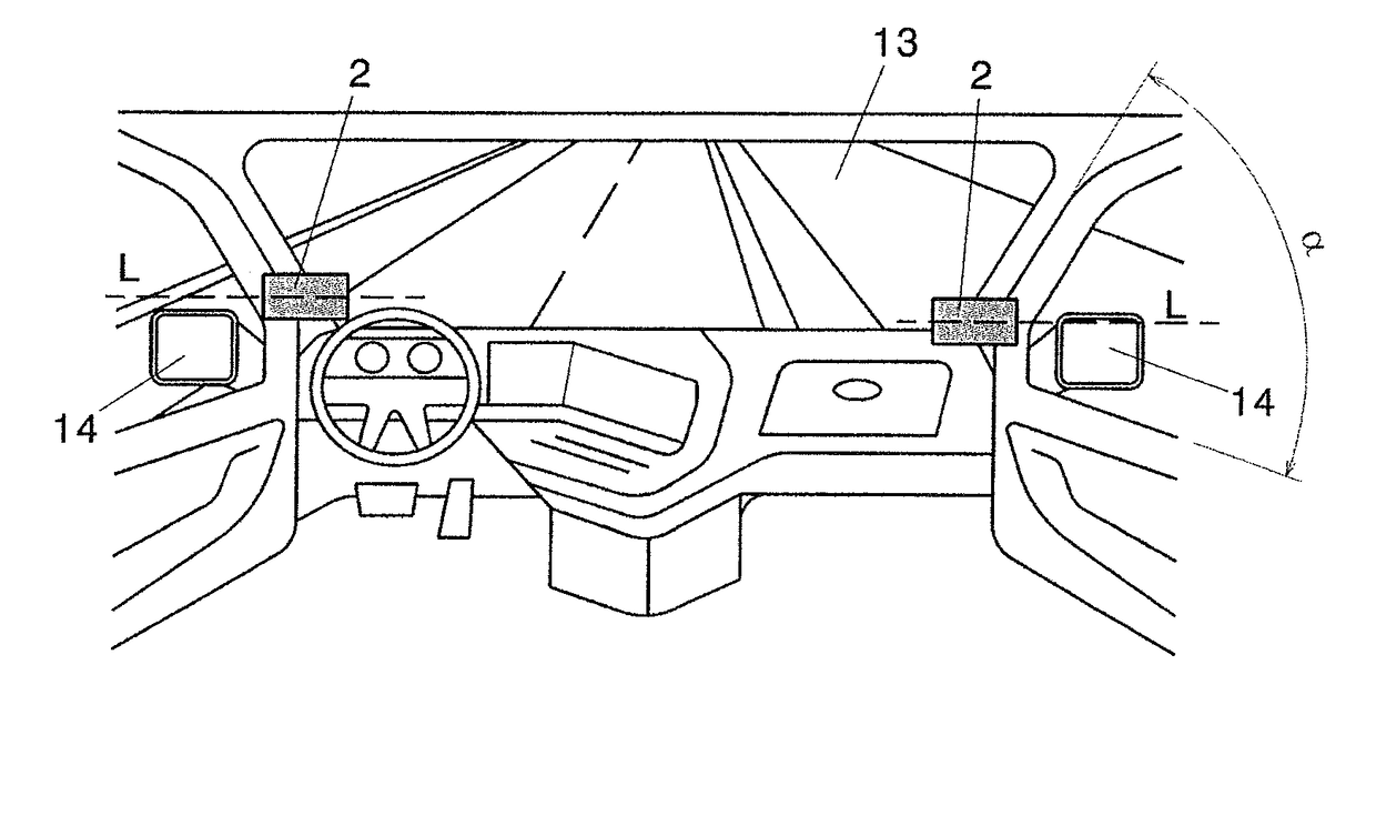
However, for certain commercial vehicles, for example trucks commonly used in North America, it is often difficult to appropriate arrange the display device within a driver's cab of the commercial vehicle, because an inclination of the A-pillar of the driver's cab is substantially less than 90° with respect to the horizontal plane, i.e. an angle of slope of the glass windshield is typically less than 90°, so that it is difficult to arrange the display device such that the driver of the commercial vehicle can easily monitor fields of view displayed on the display device.

Method used


Image

  • System for Visually Depicting Fields of View of a Commercial Vehicle
  • System for Visually Depicting Fields of View of a Commercial Vehicle
  • System for Visually Depicting Fields of View of a Commercial Vehicle

Examples


Embodiment Construction

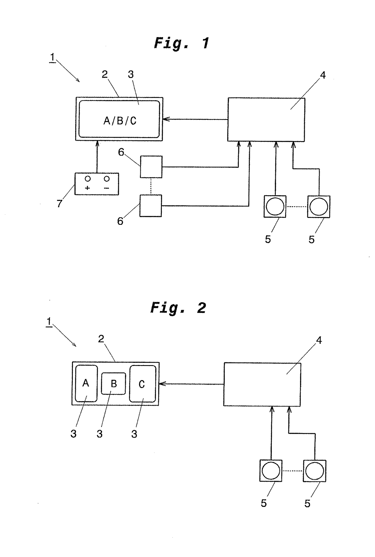
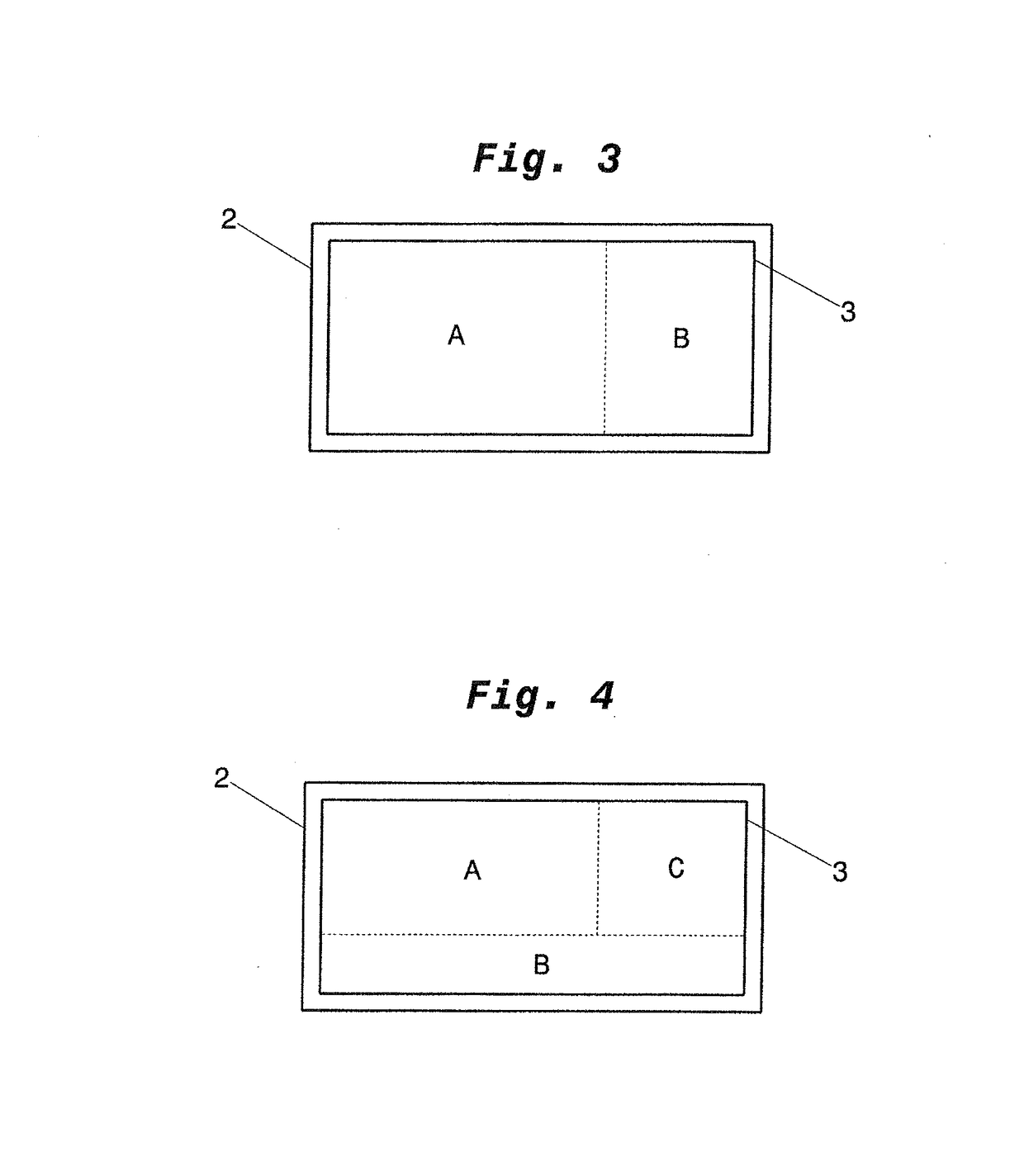
[0038]FIGS. 1 and 2 each schematically show a system 1 for visually depicting prescribed fields of view of a commercial vehicle. As shown in FIG. 1, the system comprises a display device 2 including a single display unit 3, whereas according to FIG. 2, a plurality of display units 3 is provided. This / these display unit(s) 3 is / are disposed in the driver's cab of the commercial vehicle, as described in more detail below with reference to FIGS. 6 to 9.

[0039]Further, the system 1 according to the present teaching and shown in FIGS. 1 and 2 includes e.g. at least one CPU 4 or other computing unit(s) for processing the information captured by one or more image capture units 5 and for supplying this processed information to the display unit(s) 2 in the form of the prescribed fields of view according to the selected depiction, for example bird's eye view or perspective. The image capture units 5 as shown in FIGS. 1 and 2 can be provided in an arbitrary number as required, i.e. in accordanc...


PUM


Abstract

System for visually depicting fields of view for a commercial vehicle within a driver's cab of the commercial vehicle, the system having at least one display device disposed within the driver's cab and having at least one display unit being configured to display at least one field of view, wherein the at least one display device is configured to be arranged within the driver's cab of the commercial vehicle such that the longitudinal axis thereof is substantially horizontally aligned.

Description

BACKGROUND OF THE INVENTION1. Field of the Invention[0001]The present invention relates to a system for visually depicting fields of view of a commercial vehicle within a driver's cab of the commercial vehicle.2. Description of the Related Art[0002]In motor vehicles, “fields of view” are for example legally-prescribed (required by law) or in any other way individually defined in accordance with the type of the motor vehicle, such as e.g. motor cycles, motor vehicles for transporting passengers, motor vehicles for transporting goods, etc. The fields of view must be provided by one or more “device for indirect viewing”, which is conventionally a mirror, and the fields of view must be visible or viewable by a driver sitting in the driver's seat using the device(s) for indirect viewing. Depending upon the type of the vehicle and, in particular, which areas around the vehicle that can be directly seen by the driver, different legal provisions require that certain fields of view can be se...

Claims


Application Information

Patent Timeline
IPC IPC(8): H04N5/232G06K9/00B60R1/00
CPCH04N5/23293G06K9/00791B60R1/00B60R2300/40B60R2300/202B60R2300/8026B60R2300/105G06V20/56H04N23/635B60R1/25
Inventor LANG, WERNER
Owner MEKRA LANG GMBH & CO KG
Learn More