Adapter and tip for an air and water dental syringe device

Active Publication Date: 2016-10-27
PAC DENT INC
View PDF3 Cites 6 Cited by
  • Summary
  • Abstract
  • Description
  • Claims
  • Application Information

AI Technical Summary

Benefits of technology

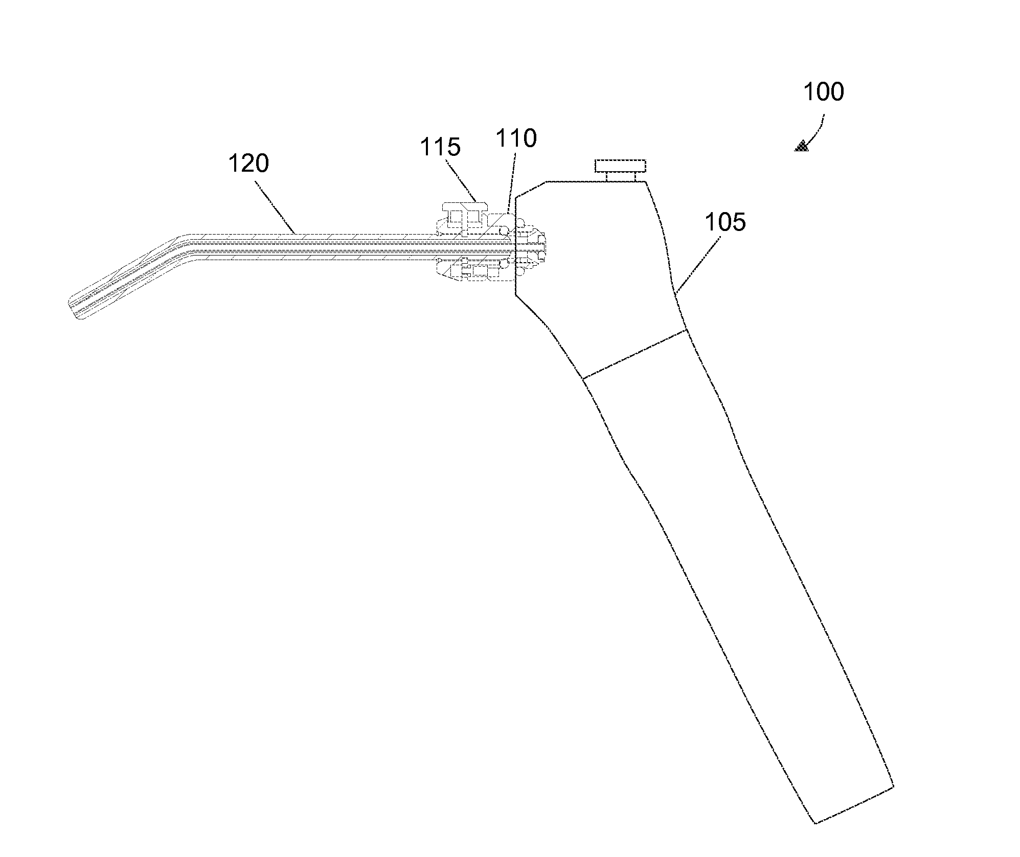
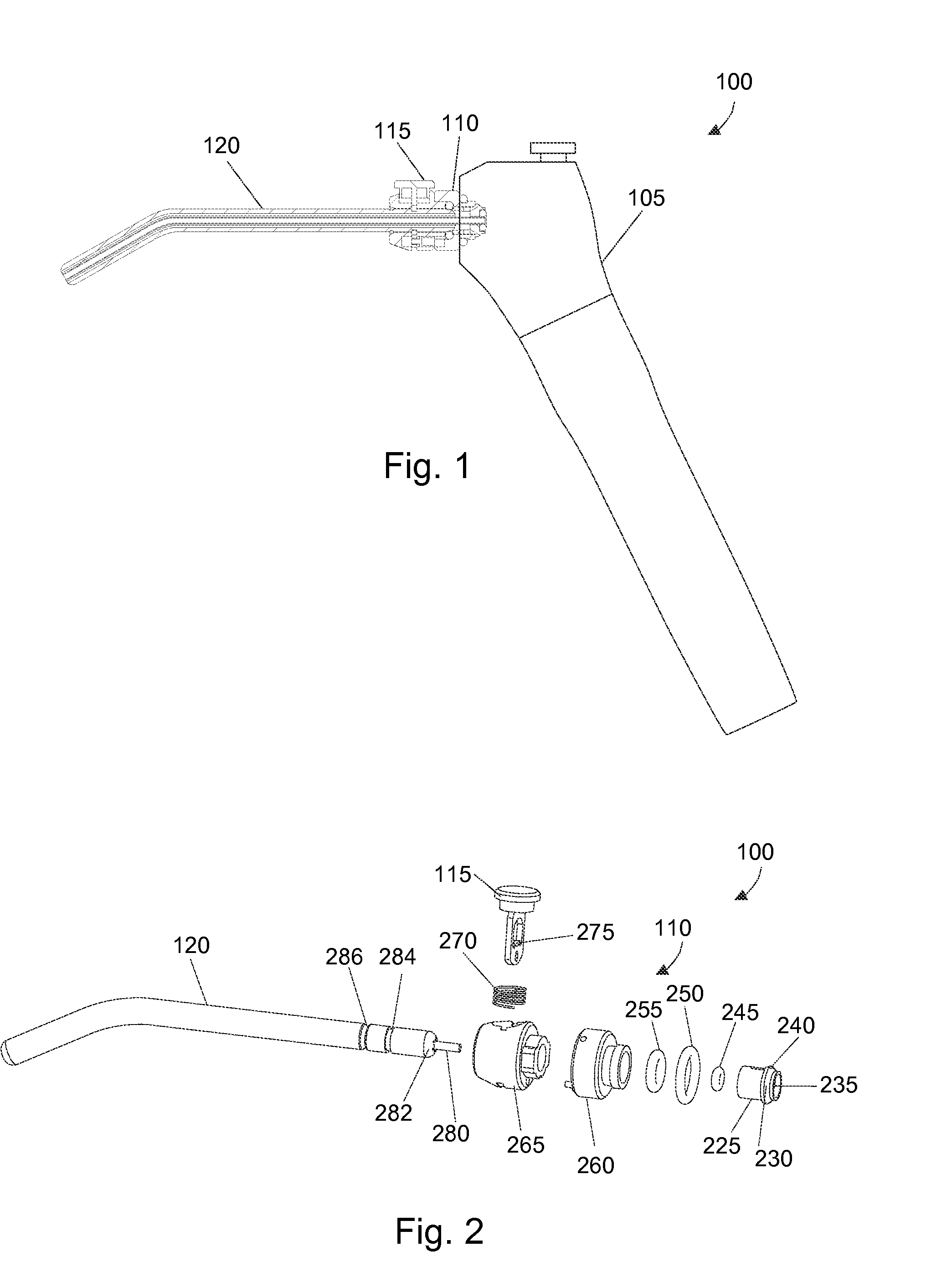
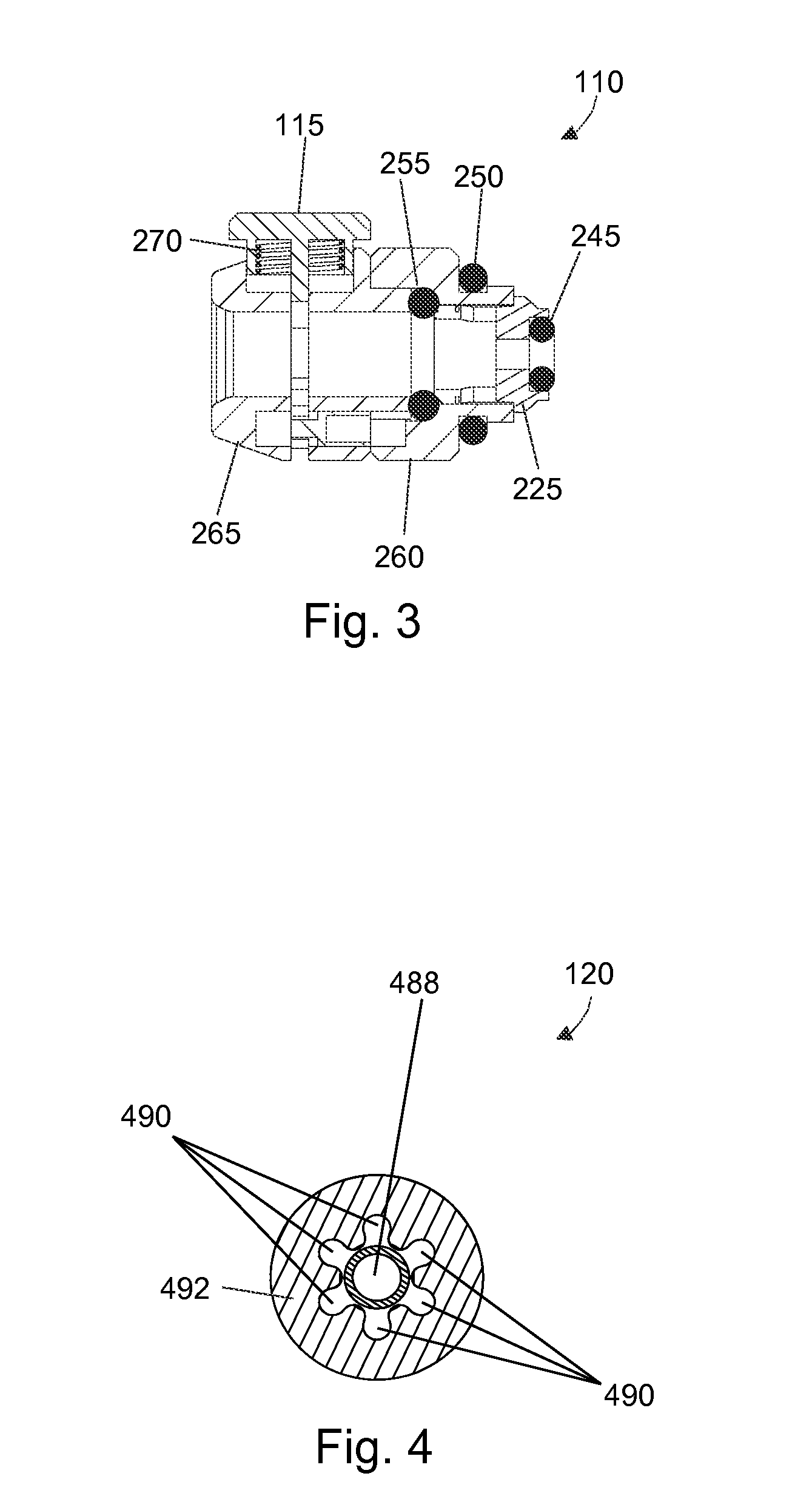
[0017]An advantage of the dental syringe device is a release component that allows the tip and the adapter connected to the syringe body to quickly and easily adapt to each other. The release component can be a manually depressible button that quickly disconnects the tip when pressed and quickly connects the tip when pressed and released. To further improve adaptation, the syringe tip has a locking groove that couples with the adapter to prevent the syringe tip from dislodging. Further, the syringe tip has an additional groove, referred to herein as a secure seating indicator, to provide visual affirmation to the medical professional that the syringe tip is properly seated in the adapter.
[0018]Another advantage is large and uniform air channels that increase the air flow through the adaptor and the tip to achieve sufficient and consistent air flow and even water sprays. Further, the larger inner diameter of the syringe tip further increases its rigidity, enabling the user to use it as a cheek retraction device during use. Moreover, this invention has a bigger cross-section as well

Problems solved by technology

A problem with disposable dental syringe devices is effectively connecting and disconnecting the tip to the dental syringe body.
Most early dental syringe devices did not have an adapter, which presented a risk of cross contamination from reuse of the dental syringe body.
However, conventional adapters are not easy to use because they do not allow the tips to be quickly and easily connected and disconnected from the body of the dental syringe.
Another problem with conventional dental syringe devices is achieving sufficient and consistent air flow through the device.
Conventional tips have air channels with very small and uneven diameters which produce inadequate air-flow which generate uneven water sprays.
A further problem with conventional dental syringe devices is that new disposable tips are made of a

Method used


Image

  • Adapter and tip for an air and water dental syringe device
  • Adapter and tip for an air and water dental syringe device
  • Adapter and tip for an air and water dental syringe device

Examples


Embodiment Construction

[0025]Before the present composition, methods, and methodologies are described, it is to be understood that this invention is not limited to particular compositions, methods, and experimental conditions described, as such compositions, methods, and conditions may vary. It is also to be understood that the terminology used herein is for purposes of describing particular embodiments only, and is not intended to be limiting, since the scope of the present invention will be limited only in the appended claims.

[0026]As used in this specification and the appended claims, the singular forms “a”, “an”, and “the” include plural references unless the context clearly dictates otherwise. Unless defined otherwise, all technical and scientific terms used herein have the same meaning as commonly understood by one of ordinary skill in the art to which this invention belongs. Any methods and materials similar or equivalent to those described herein can be used in the practice or testing of the inven...


PUM


Abstract

A dental syringe device that provides air and water to a dental patient. The device includes an adapter that connects a dental tip to a dental syringe body. The dental syringe body provides a conventional syringe body with a handle for a dentist to hold onto and a source of air and water. The tip delivers the air and water to the dental patient. The adapter is an improved adapter having a unique release and attachment component allowing for a quick connect and disconnect between the dental syringe body and the tip. The tip advantageously includes an inner portion with large and uniform air channels for smooth transfer of air and an outer portion made from a rigid plastic that provides an improved cheek retraction feature.

Description

BACKGROUND OF THE INVENTION[0001]1. Field of Invention[0002]The present invention relates generally to delivering air and water from a dental syringe device to a dental patient, and specifically, to an improved tip of the device and adapter of the device that connects a dental syringe body of the device to the tip.[0003]2. Description of Related Art[0004]Syringes mechanically pump liquid or gas through a cylindrical tube, referred to as a barrel, using a mechanical plunger that can be pushed and pulled. Syringes include a tip, also referred to as a needle or nozzle, that dispense the liquid or gas pumped through the tube. Syringes are often used to administer medical injections, apply compounds such as glue, and extract liquid samples from a medial patient such as withdrawing blood from a vein.[0005]In the dental field, a dental engine is located nearby the patient and the dentist, where the dental engine is a large appliance that typically includes a small table to hold an instrume...

Claims


Application Information

Patent Timeline
IPC IPC(8): A61C17/02A61C17/022
CPCA61C17/022A61C17/0202A61C17/0217
Inventor WANG, DANIELHU, TAOSHENGTAO, BOYANG, XIAO
Owner PAC DENT INC
Why Eureka
Try Eureka