Power transmitting device for vehicle

a transmission device and vehicle technology, applied in the direction of electric propulsion mounting, brake system, gearing, etc., can solve the problems of reducing the oil level in the oil reservoir, reducing the efficiency of power transmission in driving and energy regeneration, and reducing fuel economy, so as to suppress the effect of oil level reduction

Inactive Publication Date: 2009-06-23
HONDA MOTOR CO LTD
View PDF8 Cites 29 Cited by
  • Summary
  • Abstract
  • Description
  • Claims
  • Application Information

AI Technical Summary

Benefits of technology

[0012]It is therefore an object of the present invention to provide a power transmitting device for a vehicle which can suppress a reduction in oil level in an oil reservoir due to the splash-up of oil by a pinion gear, thereby preventing the occurrence of aeration during turning of the vehicle, for example.
[0013]It is another object of the present invention to provide a power transmitting device for a vehicle having a planetary carrier with a plurality of connecting portions wherein each connecting portion is improved in shape to ensure both torsional rigidity and bending rigidity with a minimum weight.

Problems solved by technology

As a result, power transmission efficiency in driving and in energy regeneration is reduced to cause a reduction in fuel economy.
As a result, the oil level in the oil reservoir is lowered and an oil inlet of an oil strainer is therefore exposed to the atmosphere in turning, sudden starting, uphill running, or downhill running of the vehicle, causing the occurrence of aeration such that the air is mixed into the oil.
The occurrence of such aeration causes a reduction in thrust force of a clutch in a hydraulic control system, resulting in difficulty of clutch control.
Further, in the case that each connecting portion of the planetary carrier has an arcuate shape, torsional rigidity against a gear reaction can be easily ensured, but it is disadvantageous in bending rigidity in the radial direction.
There is a case that the rotor of the electric motor may be forcibly rotated at high speeds according to the circumstances, causing an increase in loss in the electric motor and the production of undesired friction on the axles.

Method used


Image

  • Power transmitting device for vehicle
  • Power transmitting device for vehicle
  • Power transmitting device for vehicle

Examples


Embodiment Construction

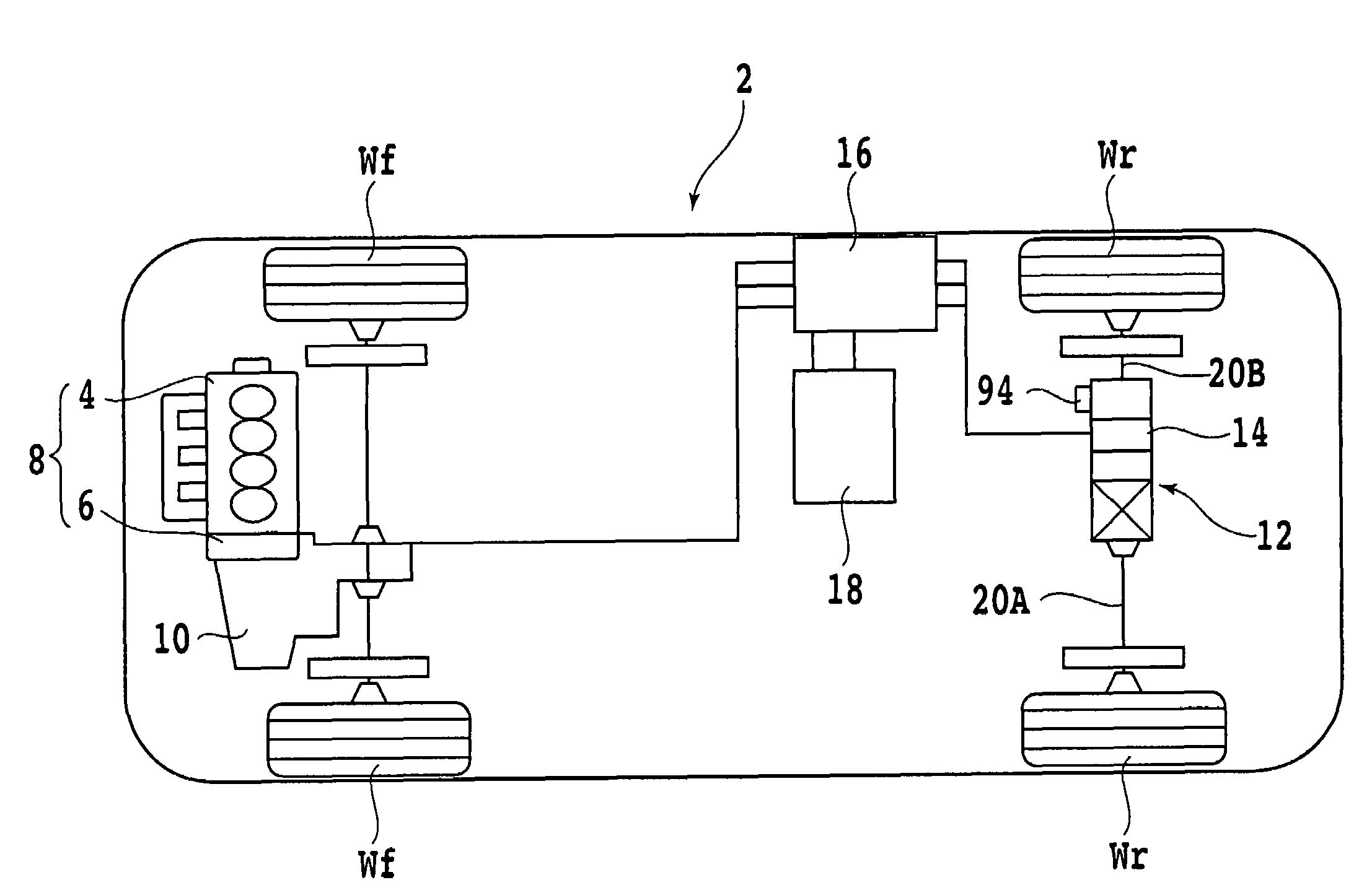
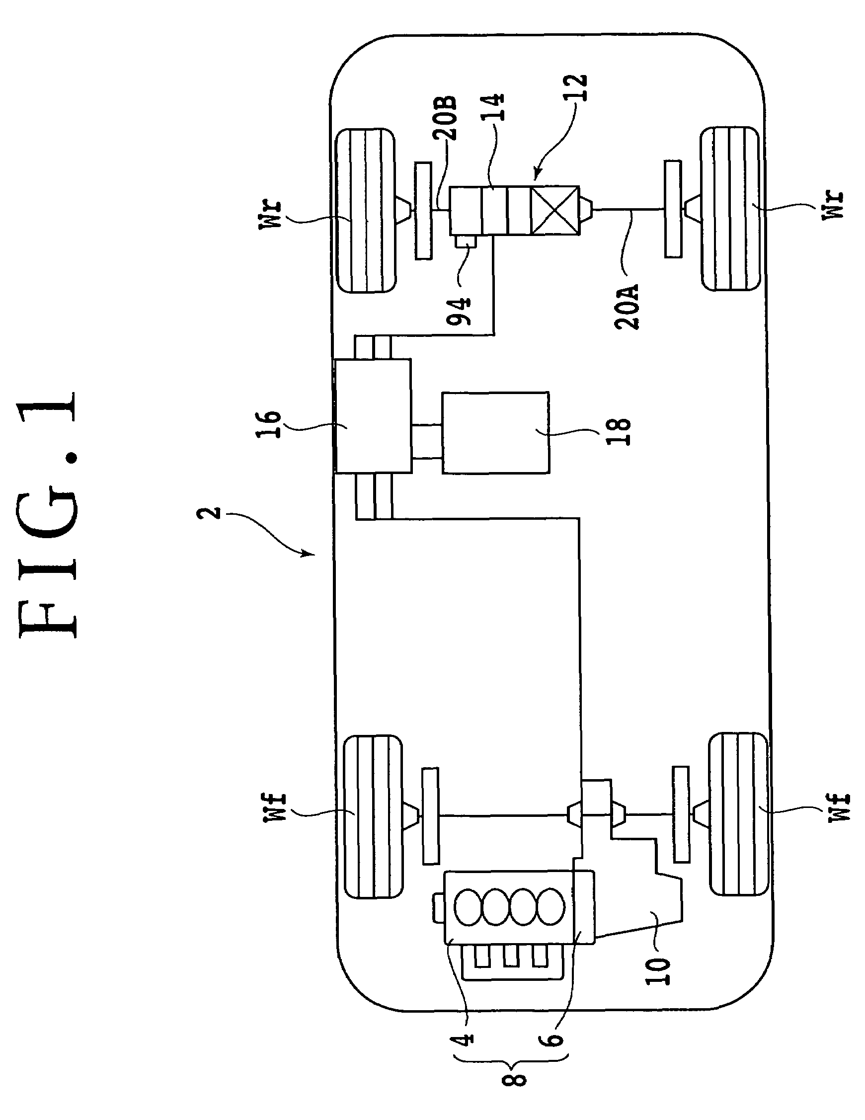
[0039]Referring first to FIG. 1, there is shown a driving mechanism in a vehicle to which the power transmitting device of the present invention is suitably applied. The vehicle 2 is a hybrid vehicle having a drive unit 8 configured by connecting an internal combustion engine 4 and an electric motor 6 in series. Power from the drive unit 8 is transmitted through a transmission 10 to front wheels Wf. On the other hand, a power transmitting device 12 according to the present invention is provided independently of the drive unit 8, and power from the power transmitting device 12 is transmitted to rear wheels Wr. The power transmitting device 12 includes an electric motor 14 for driving the rear wheels Wr. The electric motor 6 of the drive unit 8 and the electric motor 14 of the power transmitting device 12 are connected through a power drive unit (PDU) 16 to a battery 18. The supply of electric power from the battery 18 to the electric motors 6 and 14 and the regeneration of energy fro...


PUM


Abstract

A power transmitting device for a vehicle for transmitting a driving force from a driving source to right and left axles. The power transmitting device includes a housing, a planetary gear type speed reducing mechanism connected to the driving source, a differential gear unit arranged in coaxial relationship with the planetary gear type speed reducing mechanism and connected to the right and left axles, and an oil reservoir provided in a lower region of the housing. The differential gear unit has a differential case formed integrally with a planetary carrier of the speed reducing mechanism. The planetary carrier includes first and second annular members axially spaced apart from each other and a plurality of connecting portions for connecting the first and second annular members, each of the connecting portions having a substantially V-shaped configuration opening outward in the radial direction of the first and second annular members.

Description

BACKGROUND OF THE INVENTION[0001]1. Field of the Invention[0002]The present invention relates to a power transmitting device for a vehicle for transmitting a driving force from a driving source such as an electric motor through a differential gear unit to right and left axles of the vehicle, and more particularly to a power transmitting device for a vehicle in which an electric motor for driving the axles, a planetary gear type speed reducing mechanism, and a differential gear unit are arranged in coaxial relationship with the axles.[0003]2. Description of the Related Art[0004]Proposed in U.S. Pat. No. 441,877 is a power transmitting device for a vehicle having a structure such that right and left axles of the vehicle are connected to a differential gear unit and a driving force from an electric motor coaxially provided on the outer circumference of one of the right and left axles is transmitted through a planetary gear type speed reducing mechanism to the differential gear unit. In...

Claims


Application Information

Patent Timeline
Patent Type & Authority Patents(United States)
IPC IPC(8): F16H37/08B60K17/16B60T1/06F16H1/28F16H1/36F16H48/08H02K7/10
CPCB60K6/36B60K6/365B60K6/48B60K6/52B60K17/356B60K2001/001F16H1/28F16H48/08Y02T10/6221Y02T10/6265Y02T10/62
Inventor KIRA, NOBUHIRONAKAZATO, YUICHI
Owner HONDA MOTOR CO LTD
Why Eureka
Try Eureka