Passive exoskeleton

a passive, exoskeleton technology, applied in the direction of rocking horses, instruments, applications, etc., can solve the problems of limited amount of weight an individual may carry using a traditional backpack, inconvenient use of devices, and inability to carry devices

Inactive Publication Date: 2009-08-11
HRL LAB +2
View PDF29 Cites 20 Cited by
  • Summary
  • Abstract
  • Description
  • Claims
  • Application Information

AI Technical Summary

Benefits of technology

[0010]The passive exoskeleton comprises a body member for attaching proximate a portion of a user's body; a sliding rod attached with the body member; and a ground surface engage-able foot analog attached with the sliding rod. A user may place a load on the body member and thereby transfer weight of the load from the body member, through the sliding rod, and into the foot analog, causing the passive exoskeleton to support at least a portion of the load.
[0012]In another aspect, the body member is rigid, allowing the passive exoskeleton to transfer weight from the body member and through the passive exoskeleton to the ground surface.
[0018]In another aspect, the passive exoskeleton further comprises a foot connector attached with the foot analog. A user may utilize the foot connector to securely attach the foot analog with the user's foot or shoe, thereby allowing the foot analog to maintain a position proximate the user's foot.
[0019]The passive exoskeleton further comprises a body attachment attached with the body member. The body attachment is selected from a group consisting of a flexible harness, a belt, and suspenders. The body attachment is for attaching with a torso portion of a user, allowing the user to operate the exoskeleton and maintain the exoskeleton in a position proximate the user.
[0020]Additionally, the passive exoskeleton further comprises a load frame attached with the body member, whereby a user may attach a load with the load frame and thereby transfer weight from the load, through the exoskeleton and to the ground surface.

Problems solved by technology

Although the backpack functions to distribute the load, the weight of the load is transferred to the individual's hips, forcing the individual to ultimately bear the burden of the load.
Because of the necessity to bear the burden of the load, the amount of weight an individual may carry using a traditional backpack is limited.
Many orthopedic devices require the user's upper torso to be continuously used and such devices generally are not useful when upper limbs must remain free and unoccupied.
A drawback of devices made according to this particular prior art is that all of the weight is still carried by the individual's skeletal and muscular system.
The actuators required for these exoskeleton concepts consume significant power, supplies for which are either difficult to produce or are currently unavailable.
Additionally, the compact actuator (artificial muscle) technology has currently not progressed enough to make such devices practical.
Given the current state of these technologies, powered exoskeletons may not be realized for decades to come.

Method used


Image

  • Passive exoskeleton
  • Passive exoskeleton
  • Passive exoskeleton

Examples


Embodiment Construction

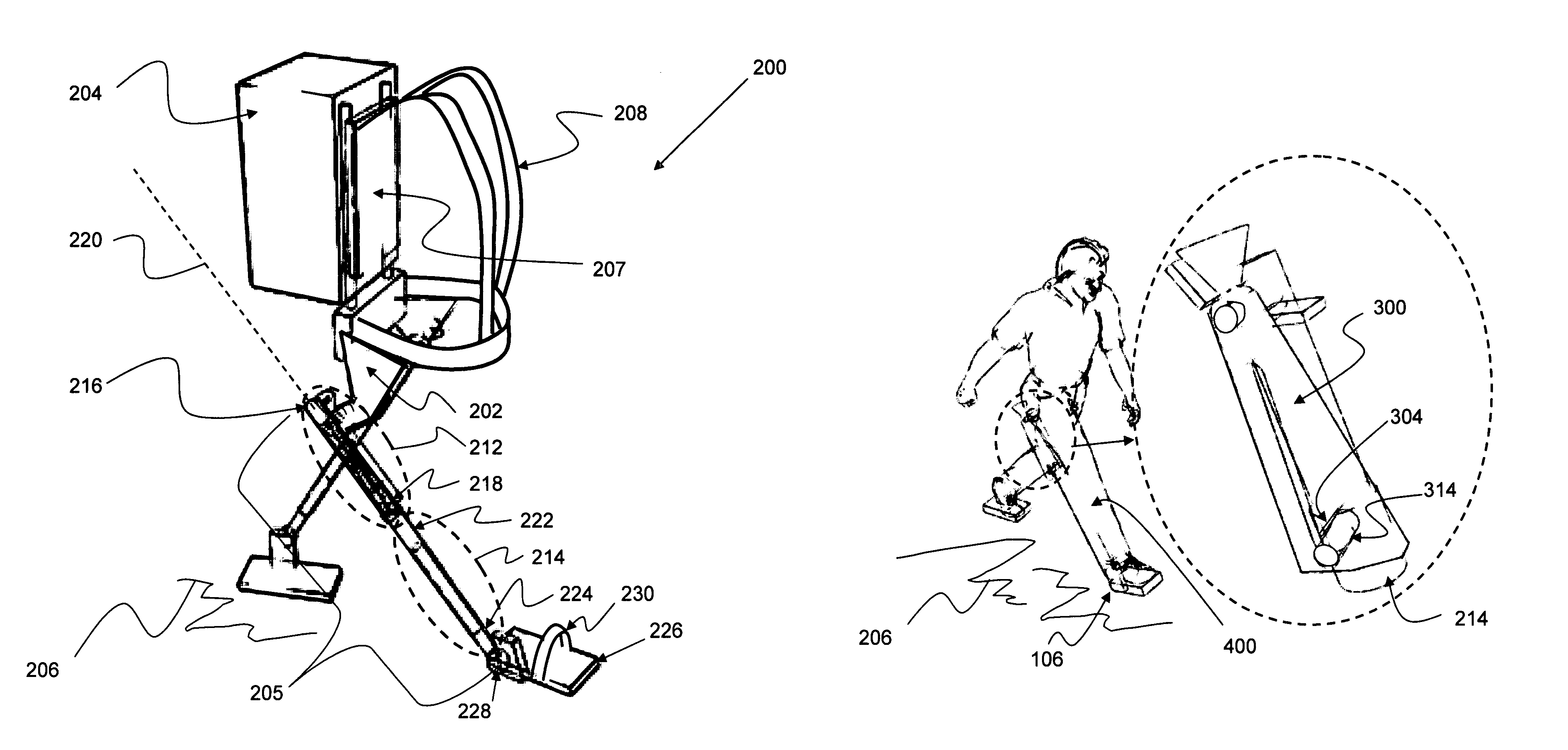
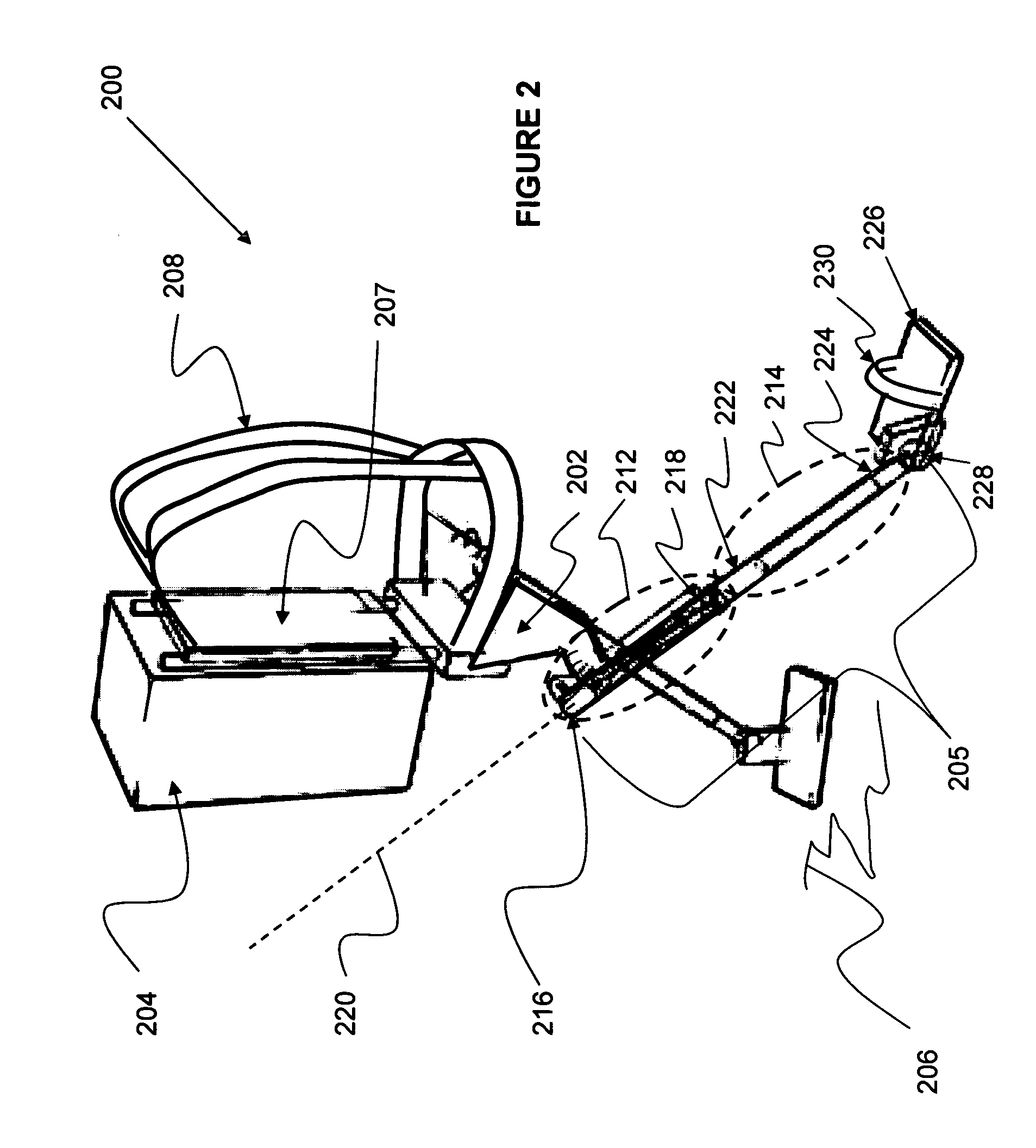
[0071]The present invention relates to a load bearing apparatus, and more particularly, to a passive exoskeleton that permits a load to be placed on the passive exoskeleton for at least a portion of the weight of the load to be transferred directly from the passive exoskeleton to a ground surface, causing the passive exoskeleton to support at least a portion of the load.

[0072]The following description, taken in conjunction with the referenced drawings, is presented to enable one of ordinary skill in the art to make and use the invention. Various modifications will be readily apparent to those skilled in the art, and the general principles defined herein may be applied to a wide range of aspects. Thus, the present invention is not intended to be limited to the aspects presented, but is to be accorded the widest scope consistent with the principles and novel features disclosed herein. Furthermore, it should be noted that unless explicitly stated otherwise, the figures included herein ...


PUM


Abstract

The present invention relates to a load bearing apparatus, and more particularly, to a passive exoskeleton whereby a load may be placed on the passive exoskeleton and thereby transfer weight of the load from the passive exoskeleton to a ground surface. The passive exoskeleton comprises a rigid body member for attaching proximate a portion of a user's body, a sliding rod attached with the body member, and a ground surface engage-able foot analog attached with the sliding rod. When a user places a load on the body member, weight of the load from is transferred from the body member, through the sliding rod, and into the foot analog, causing the passive exoskeleton to support at least a portion of the load.

Description

BACKGROUND OF INVENTION[0001](1) Field of Invention[0002]The present invention relates to a load bearing apparatus, and more particularly, to a passive exoskeleton onto which a load may be placed, with the weight of the load transferred from the passive exoskeleton to a ground surface, causing the passive exoskeleton to support at least a portion of the load.[0003](2) Background of Invention[0004]Load bearing devices have long been known in prior art. For example, backpacks with frames have long been employed to reduce a load carried by an individual's shoulders. Although the backpack functions to distribute the load, the weight of the load is transferred to the individual's hips, forcing the individual to ultimately bear the burden of the load. Because of the necessity to bear the burden of the load, the amount of weight an individual may carry using a traditional backpack is limited.[0005]Other examples of load bearing devices include orthopedic devices such as canes, crutches, an...

Claims


Application Information

Patent Timeline
Patent Type & Authority Patents(United States)
IPC IPC(8): A45C1/04A45F3/14A45F3/00A61H3/00A63B25/00A63G13/00A45F3/04A45F3/08G09G5/08
CPCA45F3/08A61H3/008A61H3/00A61H2201/1616A61H2201/1676A61H2201/1642A61H2201/165A61H2201/1652A61H2201/1621
Inventor CHU, CONRADCHU, ANDY
Owner HRL LAB
Why Eureka
Try Eureka