Micromirror array lens with optical surface profiles

a micromirror array and lens technology, applied in the direction of mirrors, mountings, instruments, etc., can solve the problems of increasing aberration caused by spherical lenses, unable to make parallel rays converge into one point, and inability to achieve high performance especially for a large aperture lens system, so as to improve the design and control of the micromirror array lens

Active Publication Date: 2009-11-17
STEREO DISPLAY
View PDF126 Cites 31 Cited by
  • Summary
  • Abstract
  • Description
  • Claims
  • Application Information

AI Technical Summary

Benefits of technology

[0012]Since each micromirror has the same function as a mirror, the reflective surface should be highly reflective. The reflective surface of the micromirror is made of metal, metal compound, metal coated with multi-layer dielectric material, metal coated with antioxidant, or multi-layered dielectric material. The metal of the reflective surface is made of silver (Ag), aluminum (Al), gold (Au), nickel (Ni), chromium (Cr), or platinum (Pt) to have high reflectivity. The metal of the reflective surface is protected by a coating layer deposited on the reflective surface with material selected from the group consisting of silicon oxide (SiO2), aluminum oxide (Al2O3), magnesium oxide (MgO), titanium oxide (TiO2), cesium oxide (CeO2), silicon nitride (Si3N4), titanium nitride (TiN), magnesium fluoride (MgF2), zinc sulfide (ZnS), zinc selenide (ZnSe), polycarbonate, polyester, polyethylene naphthalate, or fluoropolymer. In addition, the surface of the micromirror can be made to have high reflectivity using many known microfabrication processes.
[0054]The advantages of the present invention are: (1) the Micromirror Array Lens has a very fast response time because each micromirror has a tiny mass; (2) the Micromirror Array Lens reproduces an arbitrary free surface; (3) the Micromirror Array Lens provide variable optical properties including a variable focal length and / or a variable optical axis; (4) the Micromirror Array Lens has a large focal length variation because a large numerical aperture variation can be achieved by increasing the maximum rotational angle of the micromirror; (5) the Micromirror Array Lens has a variable optical axis without macroscopic movement of the lens system; (6) the Micromirror Array Lens has a high optical focusing efficiency; (7) the Micromirror Array Lens can have a large size aperture without losing optical performance. Because the Micromirror Array Lens consists of discrete micromirrors, the increase in the Micromirror Array Lens size does not cause the increase in aberration caused by shape error of the Micromirror Array Lens; (8) the Micromirror Array Lens can correct various optical effects; (9) the Micromirror Array Lens has a low cost because of the advantages of its mass productivity; (10) the Micromirror Array Lens makes the focusing system much simple; (11) the Micromirror Array Lens can have arbitrary shape and / or size.

Problems solved by technology

However, the spherical lenses cannot make parallel rays converge into one point due to aberration.
The aberration caused by spherical lenses increases as the aperture size of the spherical lenses increases.
Since many lenses are assembled, there are limitations in achieving high performance especially for a large-aperture lens system.
The large aperture lens system using spherical lens requires multiple additional large aperture lenses to correct aberration, which make the lens system bulky and impossible to use in compact portable systems.
However, conventional aspherical lenses involve with a complicated time-consuming fabrication process with high cost and have difficulty in achieving actually required lens specification.
However, the quality of the conventional Fresnel lenses is not as good as the conventional spherical lens.
Although the gradient index lens gives significant reduction in the aberration and volume, it is still expensive and difficult to fabricate.
It has complex driving mechanisms to control the relative positions of refractive lenses and a slow response time.
These attitude control systems tend to be slow, bulky, and expensive to operate.
Unfortunately, it has a slow response time typically on the order of hundreds of milliseconds.
Even though the fastest response liquid crystal lens has the response time of tens of milliseconds, it has small focal length variation and low focusing efficiency.

Method used


Image

  • Micromirror array lens with optical surface profiles
  • Micromirror array lens with optical surface profiles
  • Micromirror array lens with optical surface profiles

Examples


Embodiment Construction

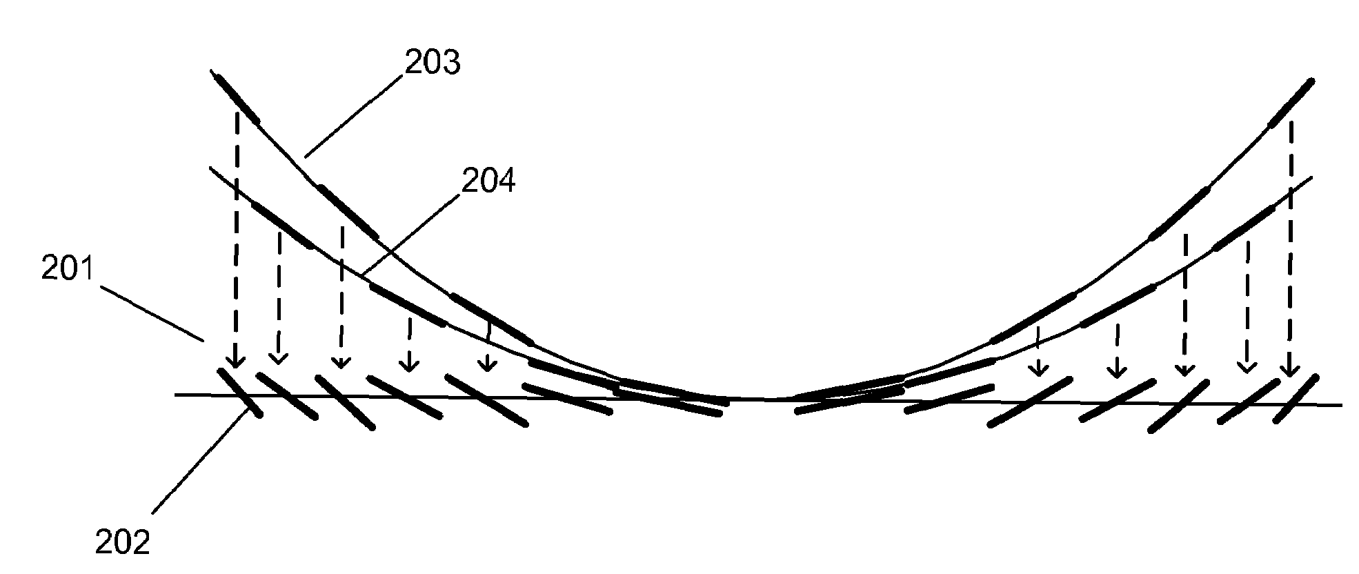
[0085]A Micromirror Array Lens comprises a plurality of micromirrors arranged on a flat or a curved surface to reflect incident light. The micromirrors are configured to have at least one motion. The Micromirror Array Lens has at least one optical surface profile to form at least one optical element reproducing at least one free surface by using the motions of the micromirrors. The free surface can be any two or three-dimensional continuous or discrete reflective surface. The Micromirror Array Lens having the corresponding optical surface profile provides optical focusing properties substantially identical to those of the free surface.

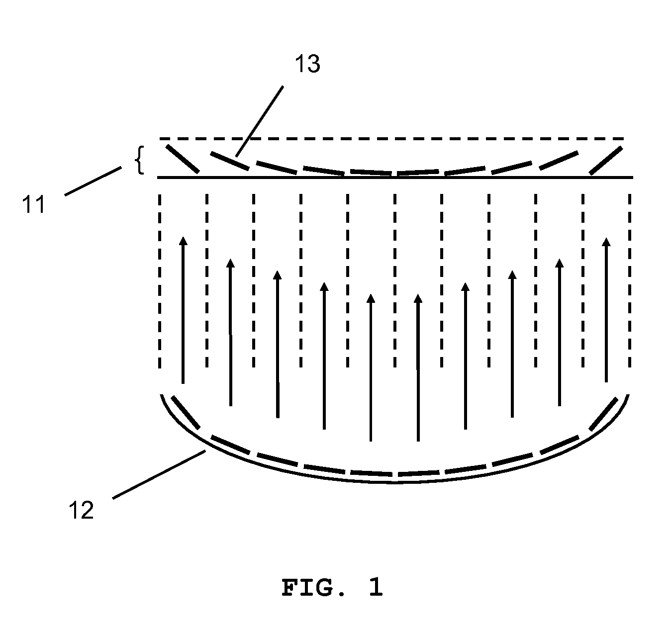
[0086]FIG. 1 illustrates the principle of a Micromirror Array Lens 11 schematically. The Micromirror Array Lens 11 comprises a plurality of micromirrors 12 and replaces an ordinary single-bodied free surface 13. The Micromirror Array Lens 11 forms a refractive Fresnel lens or a diffractive Fresnel lens that satisfies the focusing properties of the ordi...


PUM


Abstract

A Micromirror Array Lens comprises a plurality of micromirrors arranged on a flat or a curved surface to reflect incident light. Each micromirror in the Micromirror Array Lens is configured to have at least one motion. The Micromirror Array Lens forms at least one optical surface profile reproducing free surfaces by using the motions of the micromirrors. The free surface can be any two or three-dimensional continuous or discrete reflective surface. The Micromirror Array Lens having the corresponding optical surface profile provides optical focusing properties substantially identical to those of the free surface. The Micromirror Array Lens can forms various optical elements such as a variable focal length lens, a fixed focal length lens, an array of optical switches, a beam steerer, a zone plate, a shutter, an iris, a multiple focal length lens, other multi-function optical elements, and so on.

Description

REFERENCE TO RELATED APPLICATION[0001]This application is a continuation-in-part of, and claims priority to U.S. patent application Ser. No. 10 / 983,353 filed Nov. 8, 2004, U.S. patent application Ser. No. 11 / 191,886 filed Jul. 28, 2005, U.S. patent application Ser. No. 11 / 426,565 filed Jun. 26, 2006, U.S. patent application Ser. No. 11 / 743,664 filed May 2, 2007, all of which are hereby incorporated by reference.FIELD OF INVENTION[0002]The present invention relates to a Micromirror Array Lens device comprising micromirrors forming various optical elements.BACKGROUND OF INVENTION[0003]Majority of conventional lenses are spherical because spherical lenses are easy to manufacture and production cost is low. However, the spherical lenses cannot make parallel rays converge into one point due to aberration. The aberration caused by spherical lenses increases as the aperture size of the spherical lenses increases. Thus, multiple lenses have to be combined to correct the problems. Since many...

Claims


Application Information

Patent Timeline
Patent Type & Authority Patents(United States)
IPC IPC(8): G02B26/00G02B17/00G02B5/08
CPCG02B5/10G02B5/188G02B26/0833G02B17/002G02B5/1895
Inventor BAEK, SANG HYUNESOHN, JIN YOUNGCHO, GYOUNG ILSEO, CHEONG SOO
Owner STEREO DISPLAY
Why Eureka
Try Eureka