Al technical title is built by PatSnap Al team. It summarizes the technical point description of the patent document.
a technology of locking device and lock, which is applied in the field of security devices, can solve the problems making it more cumbersome and potentially less safe, and achieving the effect of compromising the safety of the motorcycl
Inactive Publication Date: 2010-02-16
WEYLAND TREVOR ADRIAN
View PDF20 Cites 29 Cited by
Summary
Abstract
Description
Claims
Application Information
AI Technical Summary
This helps you quickly interpret patents by identifying the three key elements:
Problems solved by technology
Method used
Benefits of technology
[0019]In accordance with one embodiment, a locking device comprises a cable which is fastened at one end to the device, and which passes though the face of the helmet and is detachably secured in the lock to releasably secure the helmet. The plunger or active locking element of the lock, when in locked position, acts to deny access to the fasteners securing the device to the motorcycle handlebars, so as to resist removal of the device from the handlebars. The cable is flexible, has permanently formed spiral convolutions and is partially held in place by the concave shape of the device. The device can be used to secure helmets, jackets or other items, and, in various embodiments, it can be used to lock a vehicle or item to a fixed object to deter theft of the vehicle or item.
Problems solved by technology
U.S. Pat. No. 7,159,423 to Mrdeza takes a similar approach, widening the handlebars, or the foot pegs, making the motorcycle more cumbersome and potentially less safe.
Unfortunately, this device requires modification to the article to be secured, including drilling through the helmet and potentially compromising its safety.
Method used
Image
Click on the blue label to locate the original text in one second.
Reading with bidirectional positioning of images and text.
Examples
Embodiment Construction
FIGS. 1-8
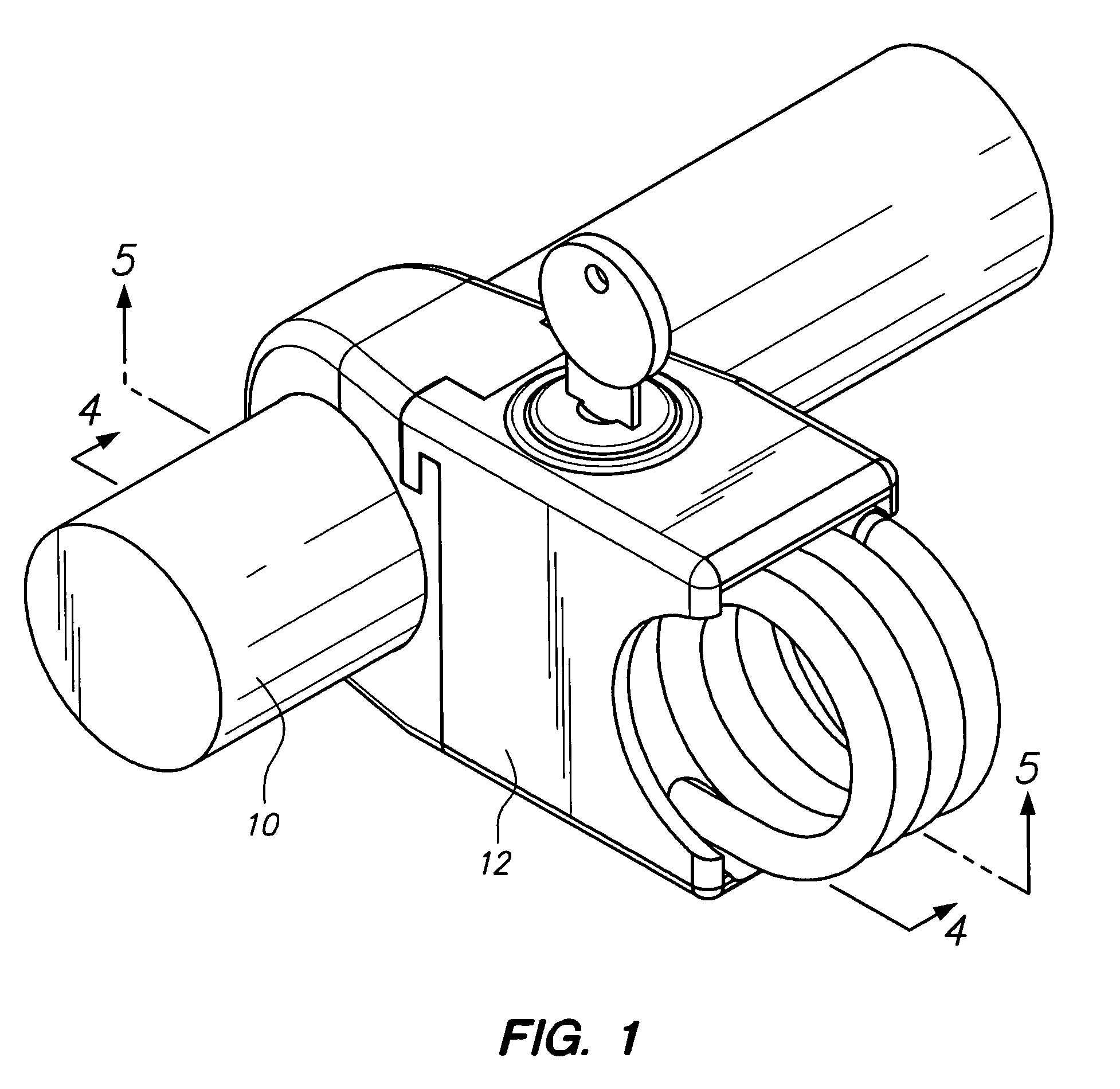
[0067]One embodiment of the locking device is illustrated in FIGS. 1-5.
[0068]A handlebar 10 and attached helmet Lock 12 are shown in FIG. 1.
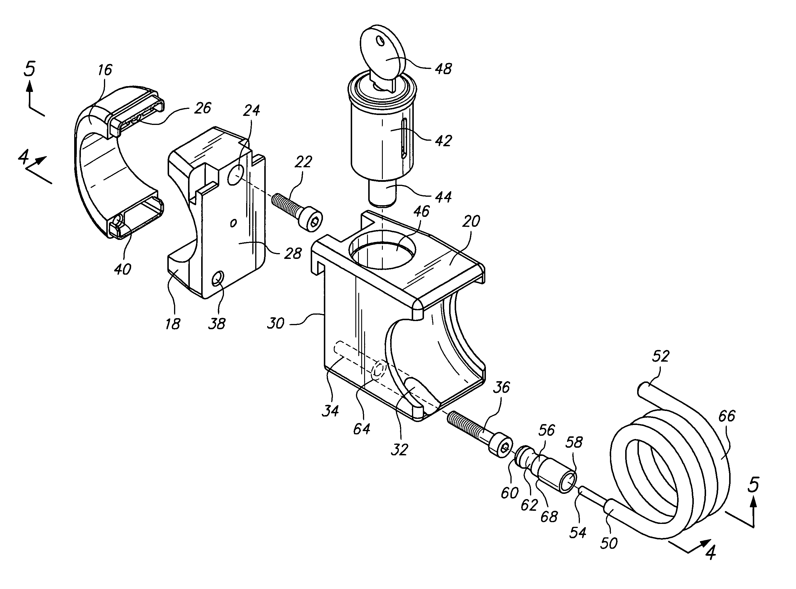
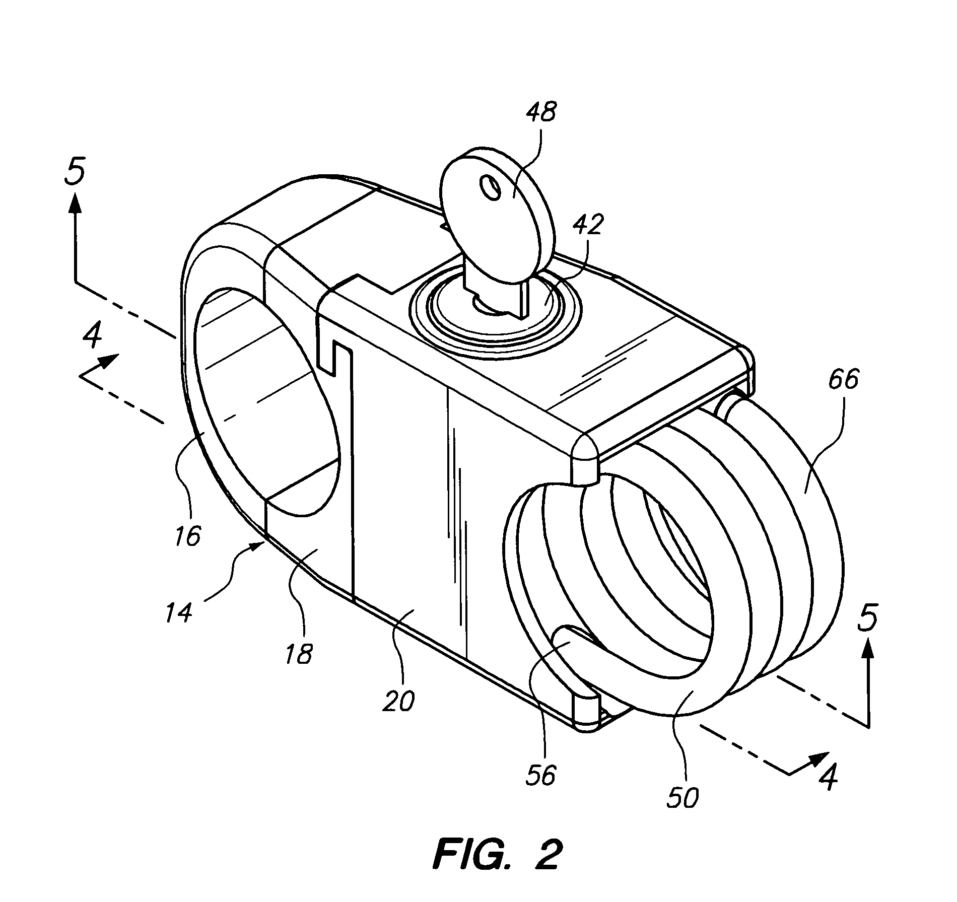
[0069]Helmet lock 12 is shown in FIG. 2 (perspective view), FIG. 3 (exploded perspective view), FIG. 4 (side view) and FIG. 5 (cross sectional view).
[0070]As shown in FIG. 2, helmet lock housing 14 comprises three sections, bar end section 16, center section 18 and lock section 20.
[0071]As shown in FIGS. 3, 4 and 5, bar end section 16 and center section 18 are secured around handlebar 10 by threaded fastener 22 through bore 24 and into bore 26. Center section 18 and lock section 20 are lined up so that faces 28 and 30 abut. Lock section 20 is provided with a through receiver bore or passageway 32 that leads to narrower bore 34. Threaded fastener 36 is inserted through bores 32, 34 and 38 into bore 40 to secure the three sections 16, 18 and 20 of lock housing 14.
[0072]Lock section 20 is provided with a lock mechanism 42 having an active ...
PUM
Abstract
One embodiment of a locking device of the type for motorcycle helmets having a cable (50) which is fastened at one end to the device, and which passes though the face of the helmet and is detachably secured in the locking device to releasably secure the helmet. The active locking element of the lock (44), when in locked position, secures the cable (50) and acts to deny access to the fastener (36) securing the device to the motorcycle handlebars, so as to resist removal of the device from the handlebars. The cable (50) is flexible, has permanently formed spiral convolutions and is partially held in place by the concave shape of the device. The device can be used to secure helmets, jackets or other items, and, in various embodiments, it can be used to lock a vehicle or item to a fixed object to deter theft of the vehicle or item. Other embodiments are described and shown.
Description
CROSS REFERENCE TO RELATED APPLICATION[0001]This application claims the benefit of PPA Ser. No. 60 / 999,347, filed 2007 Oct. 17 by the present inventor, which is incorporated by reference.US PATENT REFERENCESU.S. Pat. No. 3,782,146U.S. Pat. No. 3,910,081U.S. Pat. No. 4,028,916U.S. Pat. No. 4,065,945U.S. Pat. No. 4,233,542U.S. Pat. No. 4,274,271U.S. Pat. No. 5,791,170U.S. Pat. No. 6,227,016U.S. Pat. No. 6,536,246U.S. Pat. No. 6,609,399U.S. Pat. No. 6,629,440U.S. Pat. No. 6,698,257U.S. Pat. No. 6,923,027U.S. Pat. No. 7,159,423FEDERALLY SPONSORED RESEARCH[0002]Not ApplicableSEQUENCE LISTING OR PROGRAM[0003]Not ApplicableBACKGROUND[0004]1. Field of Invention[0005]This invention relates to security devices, specifically to a lock for securing a helmet to a motorcycle.[0006]2. Prior Art[0007]The present invention relates to a tamperproof device for locking items to a handlebar or frame of a personal vehicle, or, alternatively, for retaining a handlebar or frame to another object. In partic...
Claims
Application Information
Patent Timeline
Application Date:The date an application was filed.
Publication Date:The date a patent or application was officially published.
First Publication Date:The earliest publication date of a patent with the same application number.
Issue Date:Publication date of the patent grant document.
PCT Entry Date:The Entry date of PCT National Phase.
Estimated Expiry Date:The statutory expiry date of a patent right according to the Patent Law, and it is the longest term of protection that the patent right can achieve without the termination of the patent right due to other reasons(Term extension factor has been taken into account ).
Invalid Date:Actual expiry date is based on effective date or publication date of legal transaction data of invalid patent.