Theft deterrent system

a technology of theft prevention and system, applied in the field of theft prevention systems, can solve the problems of inability to use an electronic security system, inability to monitor goods, and inability to justify the investment in such a system

Active Publication Date: 2013-02-19
SE KURE CONTROLS
View PDF24 Cites 13 Cited by
  • Summary
  • Abstract
  • Description
  • Claims
  • Application Information

AI Technical Summary

Benefits of technology

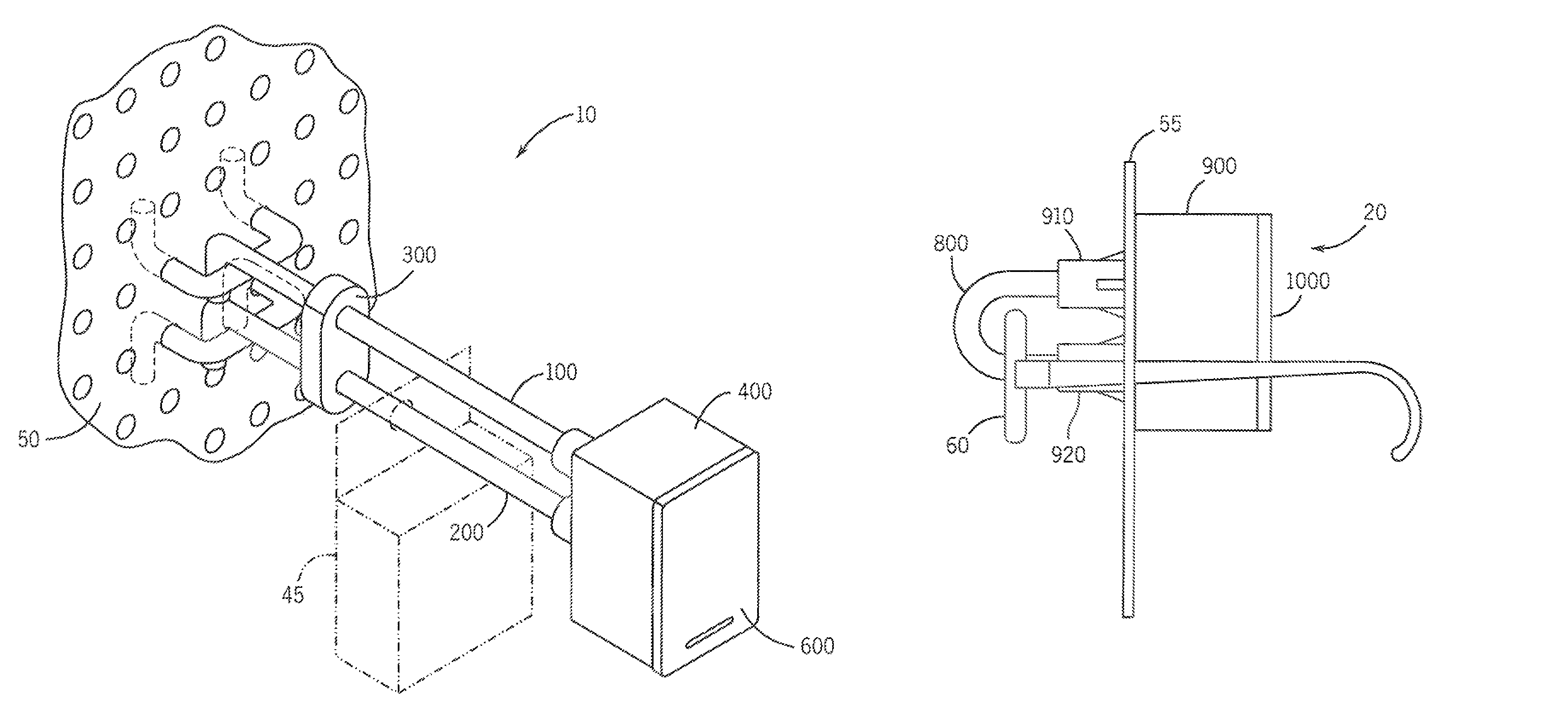
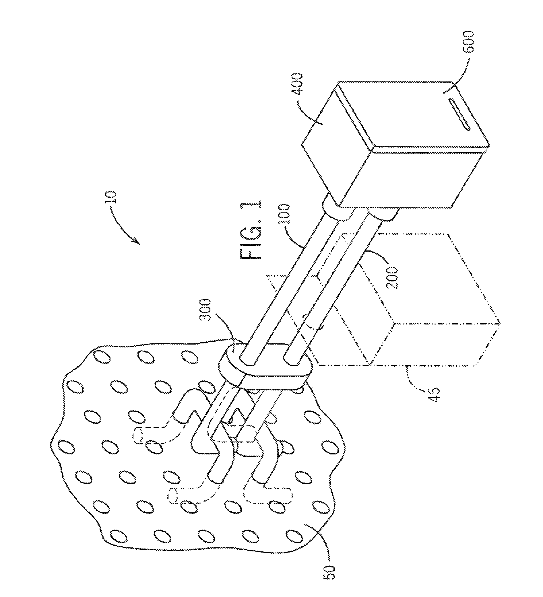
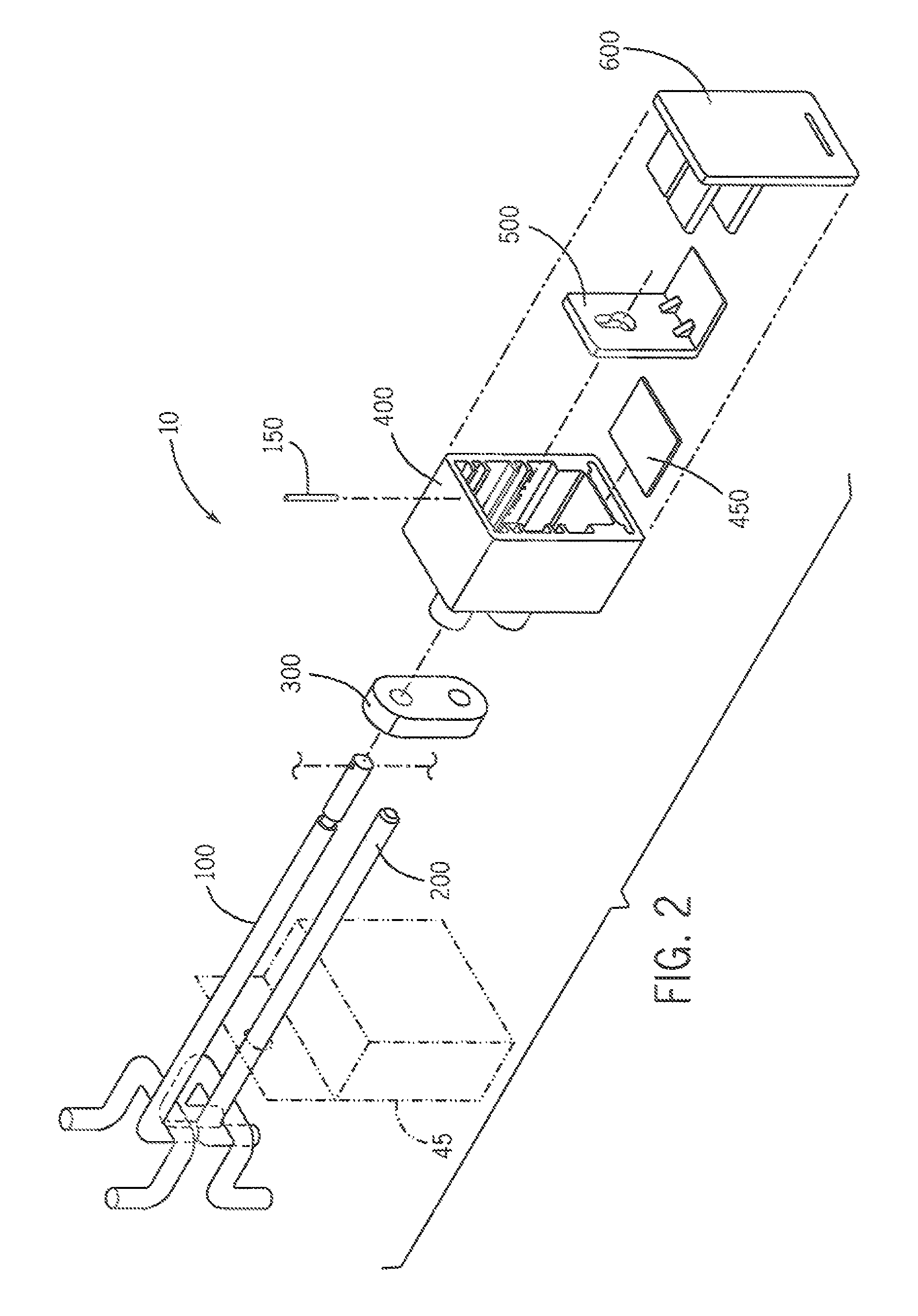
[0012]Another embodiment of the present invention is directed to a theft deterrent system for deterring theft of an apertured article and for attachment to a forward-facing side of a display panel. The theft deterrent system includes an upper elongate member that has an attachment end and an operating end, where the attachment end is attached to the forward-facing side of the display panel. The system also includes a lower elongate member for supporting the apertured article and having an attachment end and an operating end, where the attachment end is also attached to the forward-facing side of the display panel. The system also includes a magnetic key and a locking apparatus for selectively securing the article to the lower elongate member. The locking apparatus includes a housing defining an internal chamber and including a first aperture passing through the housing into the internal chamber for receiving the upper elongate member, and a second aperture adapted to receive the magnetic key. The locking apparatus also includes an engagement member extending outwardly from the main body engaging the lower elongate member and a locking member having a magnetic portion and movably disposed within the internal chamber. The locking member is adapted to selectively maintain the theft deterrent system in either a locked configuration or an unlocked configuration, depending on whether the magnetic key is inserted (unlocked) into the third aperture or not (locked). In the locked configuration, the locking member prevents longitudinal movement of the upper elongate member within the locking apparatus, and the engagement member and the lower elongate member cooperate to prevent the article from being removed from the lower elongate member. In the unlocked configuration, the locking member permits a degree of longitudinal movement of the upper elongate member within the locking apparatus such that the lower elongate member becomes disengaged from the engagement member to permit removal of the article from the lower elongate member. The lock apparatus also includes a magnetic shield disposed between the outer surface of the housing and the magnetic key when inserted into the second aperture. The magnetic shield substantially prevents a magnetic force that is external to the housing from interacting with the locking member.

Problems solved by technology

The expense of security systems and personnel used to limit losses due to theft is generally recovered by raising the price of the goods to the consumer.
However, the use of an electronic security system is not always feasible.
Sometimes, the cost of the goods to be monitored does not justify the investment in such a system.
For other types of goods, such as belts, the quantity of goods displayed is such that it would be impractical to monitor each item, as by the use of a sensor thereon.
Further, highly portable goods such as belts, small hand tools, eyeglasses and sunglasses, USB flash drives, camera memory cards and printer ink cartridges, which are small, lightweight and often relatively expensive, can be easily removed from a premise before the breach of security is detected, even when electronic systems are used.
The thief is often able to remove the article, exit promptly from the store through the adjacent exit, and become lost in crowds as are common in metropolitan areas and shopping malls.
However, when this type of system is used for relatively small, lightweight articles, the thief may be able to remove and make off with the entire quantity of articles, together with the display stand.

Method used


Image

  • Theft deterrent system
  • Theft deterrent system
  • Theft deterrent system

Examples


Embodiment Construction

[0044]Reference will now be made in detail to the preferred embodiments of the invention, examples of which are illustrated in the accompanying drawings. While the invention will be described in conjunction with the preferred embodiments, it will be understood that they are not intended to limit the invention to these embodiments. On the contrary, the invention is intended to cover alternatives, modifications and equivalents, which may be included within the spirit and scope of the invention as defined by the claims. Furthermore, in the detailed description of the present invention, numerous specific details are set forth in order to provide a thorough understanding of the present invention. However, it will be obvious to one of ordinary skill in the art that the present invention may be practiced without these specific details. In other instances, well known methods, procedures, and components have not been described in detail as not to unnecessarily obscure aspects of the present ...


PUM


Abstract

Described herein is technology for, among other things, a theft deterrent apparatus for cooperation with an elongate member attached to and extending outwardly from a forward-facing side of an article display panel. The apparatus includes a housing defining an internal chamber. The housing includes a first aperture passing through the housing into the internal chamber for receiving the elongate member, a second aperture for receiving a magnetic key, and a locking member that has a magnetic portion and is movably disposed within the internal chamber. The locking member is adapted to selectively: maintain the apparatus in locked and unlocked configurations in which the locking member respectively prevents or permits the elongate member from being at least partially withdrawn from the first aperture. Whether the locking member maintains the apparatus in the locked or unlocked configuration depends on whether or not the magnetic key is inserted into the second aperture.

Description

CLAIM OF PRIORITY UNDER 35 U.S.C. §120[0001]The present Application for Patent is a divisional of patent application Ser. No. 12 / 476,346 entitled “Theft Deterrent System” filed Jun. 2, 2009, pending, and assigned to the assignee hereof and hereby expressly incorporated by reference herein.BACKGROUND[0002]1. Field[0003]Embodiments of the present invention generally relate to theft deterrent systems as used to prevent unauthorized removal of consumer goods.[0004]2. Background[0005]Those involved in the distribution of consumer goods are constantly seeking ways to prevent unauthorized removal of goods from display areas. The expense of security systems and personnel used to limit losses due to theft is generally recovered by raising the price of the goods to the consumer. In today's highly competitive market, the successful retailer thus seeks security systems that are both economically practical and effective.[0006]Electronic theft deterrent systems have proven to be highly successful...

Claims


Application Information

Patent Timeline
Patent Type & Authority Patents(United States)
IPC IPC(8): E05B73/00
CPCA47F5/0861E05B47/004E05B47/0045E05B73/00E05B73/0035E05B67/22Y10T70/40Y10T70/5004Y10T70/7904
Inventor SURMA, TERRANCELEYDEN, ROGER J.
Owner SE KURE CONTROLS
Why Eureka
Try Eureka