Head gimbal assembly having dimple-shaft limiter and manufacturing method thereof and disk drive unit with the same

a technology of dimple shaft and limiter, which is applied in the direction of instruments, record information storage, and support for heads, etc., can solve the problems of difficult alignment of load beams, asymmetric dimple geometry, and conventional hga shock performance drawbacks, etc., and achieve good shock performance and good flying performance.

Inactive Publication Date: 2010-03-30
SAE MAGNETICS (HK) LTD
View PDF3 Cites 46 Cited by
  • Summary
  • Abstract
  • Description
  • Claims
  • Application Information

AI Technical Summary

Benefits of technology

[0009]Accordingly, a main object of the present invention is to provide a HGA that has a good shock performance and a good flying performance.
[0010]Another object of the present invention is to provide a disk drive unit that has a good shock performance and a good flying performance.
[0011]Yet another object of the present invention is to provide a method for manufacturing a HGA to improve shock performance and flying performance of the HGA.

Problems solved by technology

However, such a dimple is required to use a punch coining die or a pulsed laser energy treatment to manufacture, so the manufacturing processes are rather complicated and easy to cause the dimple geometry asymmetric.
Moreover, even if the geometry of the dimple 107′ is symmetric, as there is no special positioning mechanism, it is difficult to align the load beam 102′ with the flexure 103′ in assembly.
In additional, the conventional HGA has a drawback in shock performance.
Even a limiter is provided to the suspension 101′ to reduce the movement of the flexure 103′, but the movement can not be avoided because the clearance of the limiter gap is difficult to control.
Due to the DCF is very small (Normal DCF is 2-4 g for 30% slider and 0.1-0.3 g for 20% slider), it is difficult to test and control the DCF especially for the small size slider (such as 20%, 15%, or 10% slider).

Method used


Image

  • Head gimbal assembly having dimple-shaft limiter and manufacturing method thereof and disk drive unit with the same
  • Head gimbal assembly having dimple-shaft limiter and manufacturing method thereof and disk drive unit with the same
  • Head gimbal assembly having dimple-shaft limiter and manufacturing method thereof and disk drive unit with the same

Examples


first embodiment

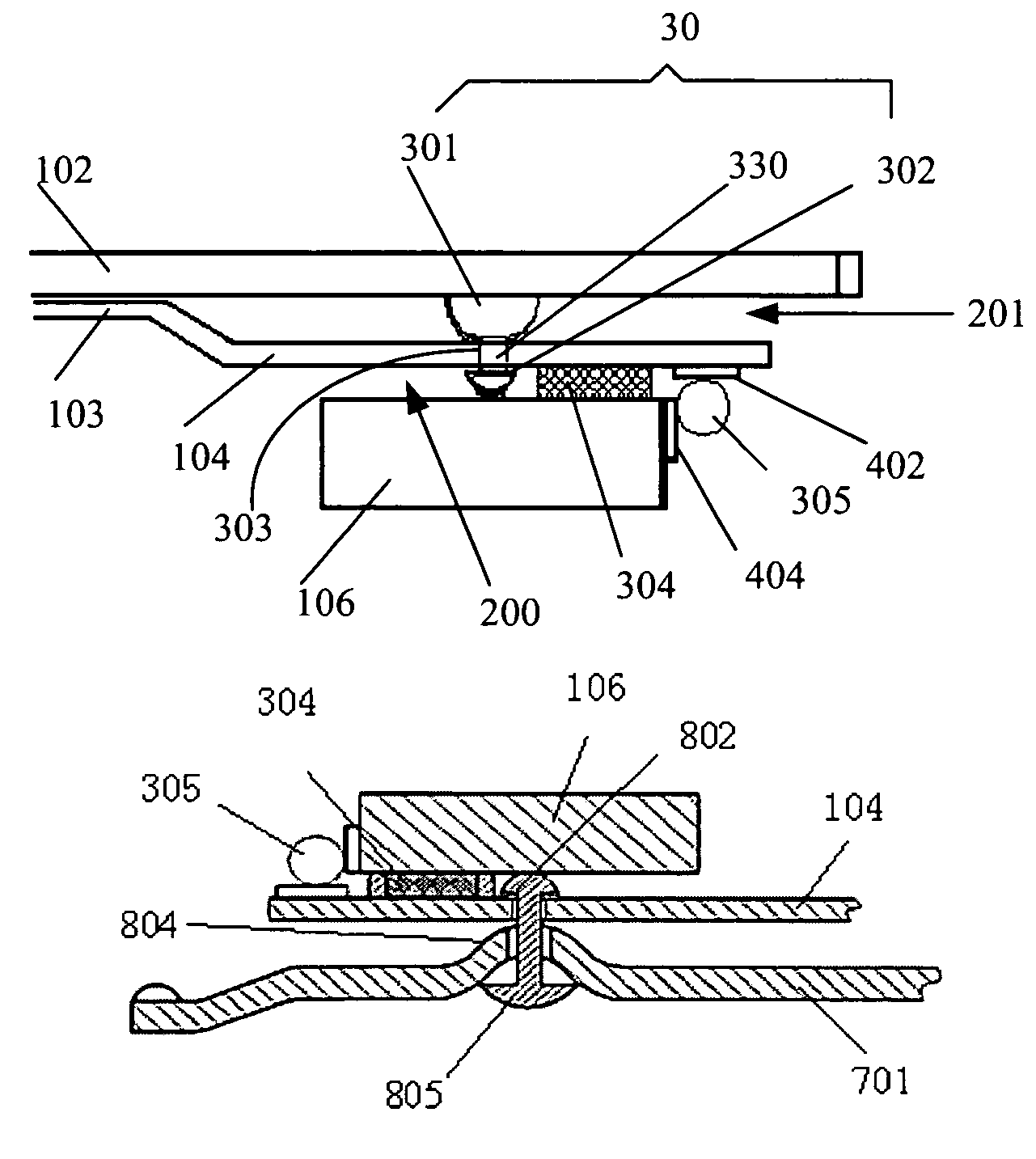
[0055]FIGS. 7a-7f are steps of manufacturing the HGA shown if FIGS. 3a-3b according to the present invention. In this embodiment, firstly, providing a slider 106, a load beam 102, a flexure 103 with a suspension tongue 104; secondly, forming a suspension through hole 303 in the suspension tongue 104 at a position corresponding to a center of the slider 106 to be mounted on the suspension tongue 104; providing a blank dimple 7 which has a first bump 301 and a stainless shaft 330 extending from the first bump 301; thereafter, fixing the first bump 301 to the load beam 102 at a position corresponding to the suspension through hole 303 by mechanical mechanism, by soldering or other suitable ways; then, pressing the flexure 103 on the load beam 102 and making the stainless shaft 330 of the blank dimple 7 extend through the suspension through hole 303 of the suspension tongue 104; forming a second bump 302 at a free end of the stainless shaft 330 so as to connect the load beam 102 and the...

second embodiment

[0058]FIGS. 8a-8e show steps of manufacturing the HGA according to the present invention. In this embodiment, firstly, providing a slider 106, a load beam 701, a flexure 103 with a suspension tongue 104; secondly, forming a suspension through hole 303 in the suspension tongue 104 at a position corresponding to a center of the slider 106 to be mounted on the suspension tongue 104, and forming a load beam through hole 801 in the load beam 701 at a position corresponding to the suspension through hole 303; forming a bow bump 804 on the load beam 701 with the load beam through hole 801 as the center of the bow bump 804; then, aligning the suspension through hole 303 with the load beam through hole 801; next, providing a blank dimple 8 which has a first bump 802 and a stainless shaft 803 extending from the first bump 802, making the stainless shaft 803 of the blank dimple 8 extend through the suspension through hole 303 and the load beam through hole 801; forming a second bump 805 at a f...

third embodiment

[0059]FIGS. 9a-9e show steps of manufacturing the HGA according to the present invention. The embodiment is similar with the embodiment shown in FIGS. 8a-8e except that the sequence and the direction of the shaft 803 extending through the load beam hole 801 and the suspension through hole 303 is different, but also achieves the same effect and function of the embodiment of FIGS. 8a-8e. As FIG. 9e and FIG. 9f show, the mounting of the slider 106 to the flexure 103 is the same with the embodiments of FIG. 8e and FIG. 8f respectively, therefore a detailed description of which is also omitted herefrom.

[0060]In the present invention, it is understandable that the material of the dimple is not limited to stainless steel. Other suitable material having certain intensity and rigidity can also be used to manufacture the dimple.

[0061]The dimple of the present invention is very easy to manufacture and an assembly accuracy thereof can be ensured so as to improve the slider fly height characteri...


PUM

PropertyMeasurementUnit
lengthaaaaaaaaaa
areaaaaaaaaaaa
diametersaaaaaaaaaa

Abstract

A HGA includes a slider and a suspension for supporting the slider. The suspension includes a load beam, a base plate, and a flexure, which are assembled together. The flexure has a suspension tongue with a suspension through hole defined therein at a position corresponding to a center of the slider mounted on the suspension tongue. A dimple is provided to connect the suspension tongue and the load beam. The dimple has a first bump, a second bump and a shaft connecting the first and the second bumps. The shaft of the dimple extends through the suspension through hole to limit the suspension tongue between the first and the second bumps. Meanwhile, a manufacturing method of the HGA and a disk drive unit with the HGA are disclosed.

Description

FIELD OF THE INVENTION[0001]The present invention relates to a disk drive unit, and more particularly to a head gimbal assembly (HGA) and its manufacturing method.BACKGROUND OF THE INVENTION[0002]In the disk drive unit industry today, different methods are used to support a slider with magnetic head to selectively read from and write to a rotating disk, one of which is called CSS (contact start stop), and the other is called load / unload, both kinds of the methods are related with a support structure or design of a suspension of a HGA in the disk drive unit.[0003]FIGS. 1a-1c illustrate a conventional HGA that includes a slider 106′, incorporating a magnetic read / write head, and a suspension 101′. The suspension 101′ includes a load beam 102′, a flexure 103′, and a base plate 105′, all of which are assembled together. The flexure 103′ provides a suspension tongue 104′ for supporting the slider 106′ thereon. A dimple 107′ is formed on a distal end of the load beam 102′ to support the s...

Claims


Application Information

Patent Timeline
Patent Type & Authority Patents(United States)
IPC IPC(8): G11B5/48
CPCG11B5/4826G11B5/4853Y10T29/49025
Inventor YAO, MINGGAOSHIRAISHI, MASASHI
Owner SAE MAGNETICS (HK) LTD
Why Eureka
Try Eureka