

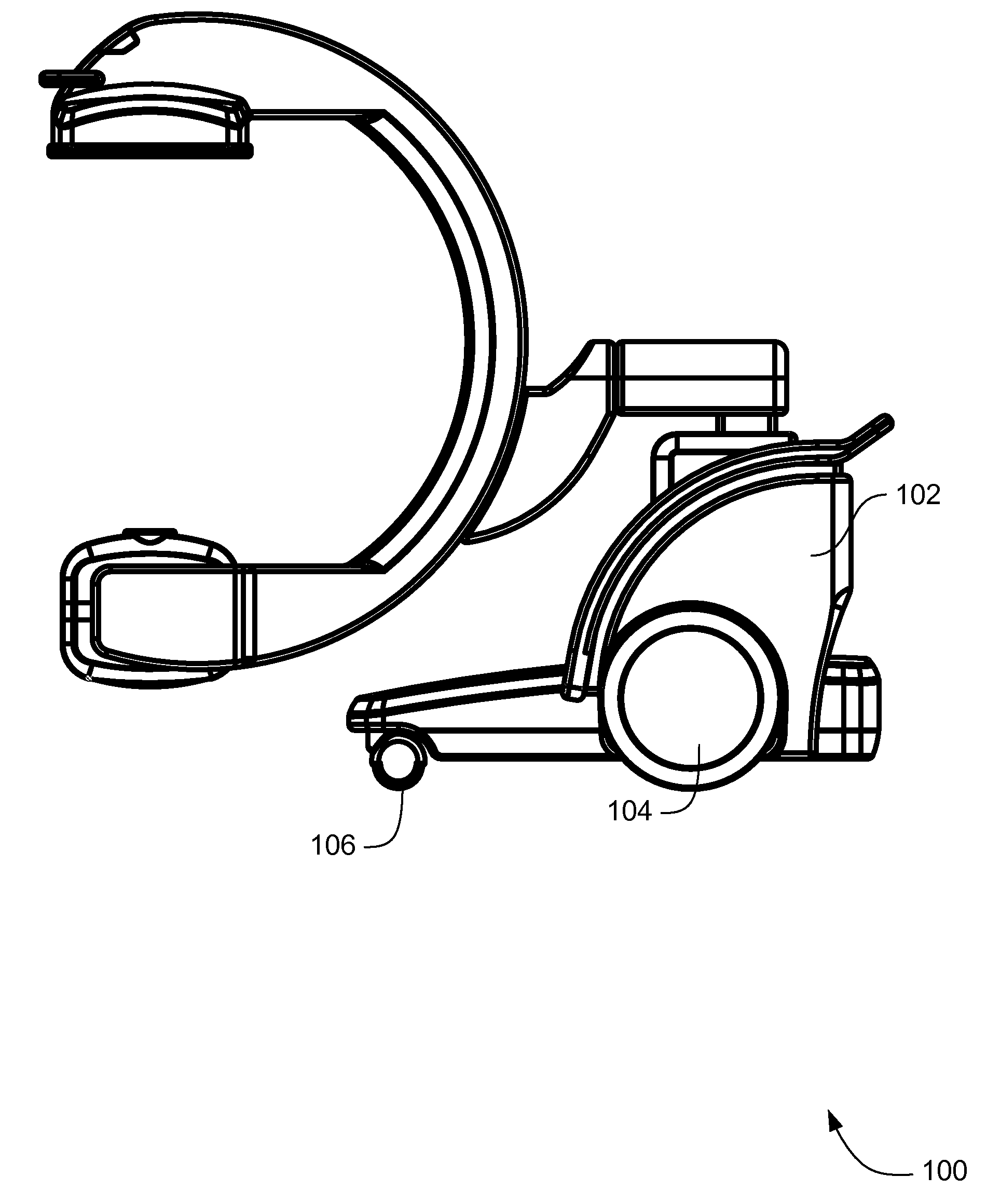
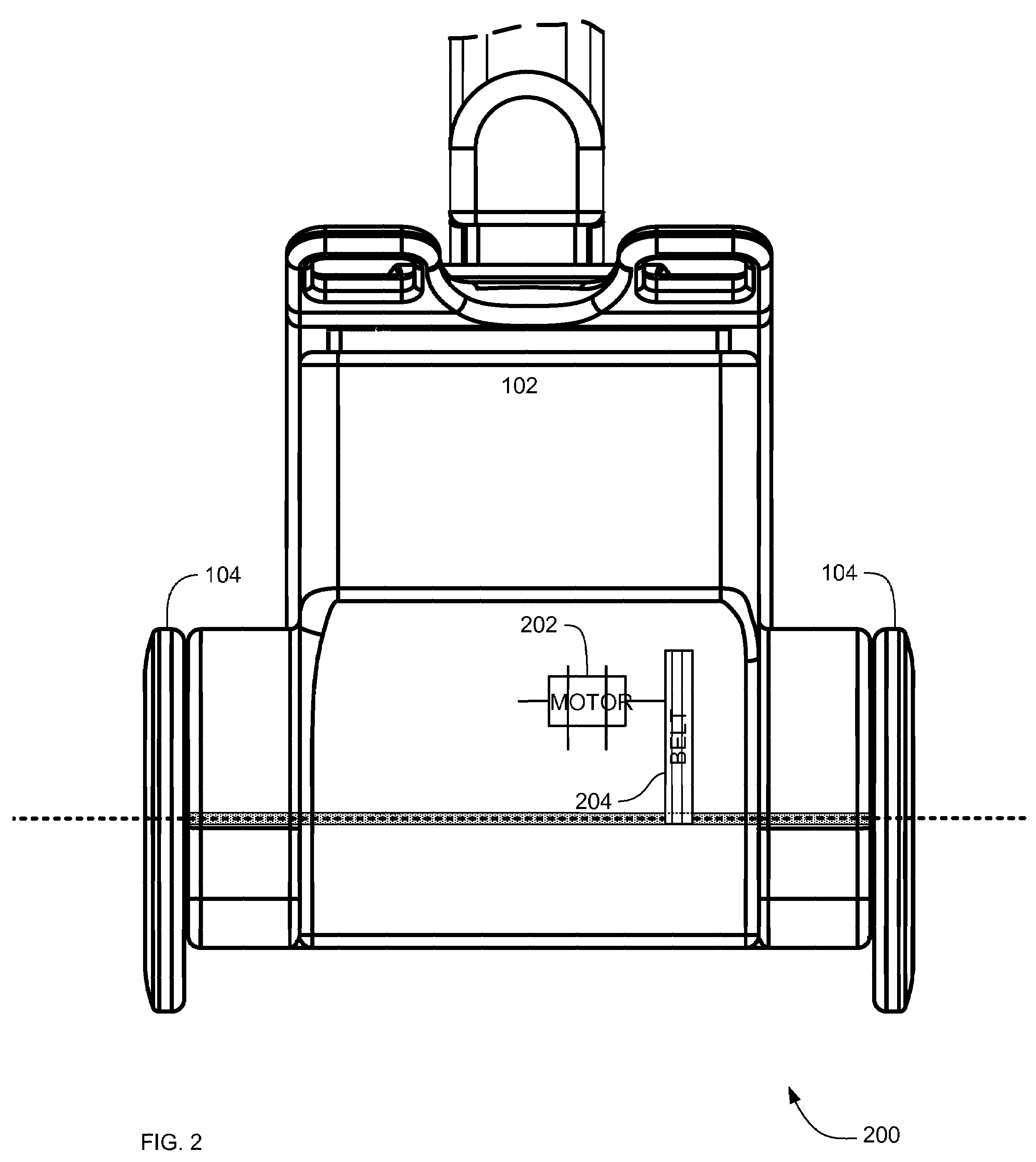
Systems, methods and apparatus of motorised independent main-wheel drive and positioning for a mobile imaging system
a technology of motorised independent main-wheel drive and mobile imaging system, which is applied in the directions of application, transportation and packaging, and non-deflectable wheel steering, etc., can solve the problems of increasing the size of the mobile c-arm system, increasing the weight, and increasing the weigh
- Summary
- Abstract
- Description
- Claims
- Application Information
AI Technical Summary
Benefits of technology
Problems solved by technology
Method used
Image


Examples
Embodiment Construction
[0027]In the following detailed description, reference is made to the accompanying drawings that form a part hereof, and in which is shown by way of illustration specific embodiments which may be practiced. These embodiments are described in sufficient detail to enable those skilled in the art to practice the embodiments, and it is to be understood that other embodiments may be utilized and that logical, mechanical, electrical and other changes may be made without departing from the scope of the embodiments. The following detailed description is, therefore, not to be taken in a limiting sense.
[0028]The detailed description is divided into five sections. In the first section, a system level overview is described. In the second section, apparatus of embodiments are described. In the third section, embodiments of methods are described. Finally, in the fourth section, a conclusion of the detailed description is provided.
System Level Overview
[0029]A system level overview of the operation...
PUM
 Abstract
Description
Claims
Application Information