Liquid crystal display apparatus and liquid crystal panel

a technology of liquid crystal display and display apparatus, which is applied in the direction of instruments, color television details, projectors, etc., can solve the problems of deteriorating image quality, affecting the quality of display images, so as to increase the image quality of displayed images and increase manufacturing efficiency

Inactive Publication Date: 2010-10-05
SONY CORP
View PDF11 Cites 17 Cited by
  • Summary
  • Abstract
  • Description
  • Claims
  • Application Information

AI Technical Summary

Benefits of technology

[0019]In particular, as described above, when the peripheral electrode is provided, such a problem may be promoted. That is, since the light transmitted through the reflection polarizing plate is incident on the light-shielding layer through the liquid crystal layer, and the light is reflected to the reflection polarizing plate through the liquid crystal layer, the light transmitted through the reflection polarizing plate may have a different polarized condition from that of the light reflected by the light-shielding layer, due to the liquid crystal layer driven with the peripheral electrode. Therefore, the occurrence of such a problem that the light is reflected again by the reflection polarizing plate, and mixed into the pixel region may be increased.
[0020]If a light-shielding film is provided on the liquid crystal panel to prevent the light transmitted through the reflection polarizing plate from being incident on the liquid crystal layer in the peripheral region, the occurrence of the above problem can be reduced. However, with the method in which the light-shielding film is provided by a single structure, a light-shielding portion has to be arranged to extend over a seal portion from an end portion of an effective display region to an end portion of one of the substrates so as to secure positional accuracy of the light-shielding film and to completely shield light while the light-shielding layer is arranged on an inner surface of the substrate of the liquid crystal display apparatus. Hence, it is difficult to irradiate the seal member with light. Thus, it is difficult to employ a photo-curable material for the seal member, and a thermosetting material has to be used instead. The liquid crystal layer may be contaminated by outgas generated by heat curing. This may deteriorate reliability. Alternatively, with the method in which the light-shielding film is provided on an inner surface and an outer surface of the one of the substrates, a step of forming the light-shielding film on the outer surface has to be performed after the liquid crystal display apparatus is assembled. Thus, in order to avoid damage on the assembled liquid crystal display apparatus, the number of steps has to be increased.
[0022]Accordingly, it is desirable to provide a liquid crystal display apparatus and a liquid crystal panel capable of increasing image quality of a displayed image, and increasing manufacturing efficiency when a reflection polarizing plate is used.
[0026]Accordingly, the liquid crystal display apparatus and the liquid crystal panel can be provided, which are capable of increasing the image quality of the displayed image, and increasing the manufacturing efficiency when the reflection polarizing plate is used.

Problems solved by technology

In the liquid crystal display apparatus, however, when the reflection polarizing plate is arranged to face a light-incident surface of the liquid crystal panel, the image quality of a displayed image may be deteriorated.
For example, the image quality of a displayed image may be deteriorated because light called “stray light” is incident on the pixel region of the liquid crystal panel.
This may cause the image quality of the displayed image to be deteriorated.
In particular, as described above, when the peripheral electrode is provided, such a problem may be promoted.
Therefore, the occurrence of such a problem that the light is reflected again by the reflection polarizing plate, and mixed into the pixel region may be increased.

Method used


Image

  • Liquid crystal display apparatus and liquid crystal panel
  • Liquid crystal display apparatus and liquid crystal panel
  • Liquid crystal display apparatus and liquid crystal panel

Examples


first embodiment

[0045]A liquid crystal display apparatus according to a first embodiment of the present invention is described below.

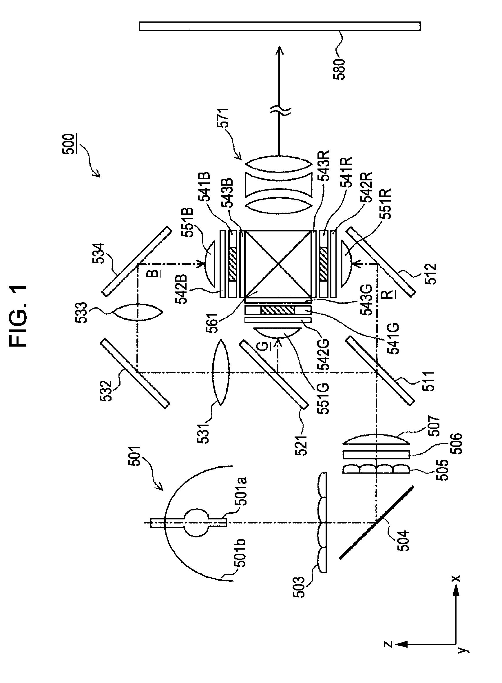
[0046]FIG. 1 is a top view showing the liquid crystal display apparatus according to the first embodiment of the present invention.

[0047]Referring to FIG. 1, a liquid crystal display apparatus 500 of this embodiment is a three-plate liquid crystal projector. The liquid crystal display apparatus 500 includes a light source 501, a first lens array 503, a first reflection mirror 504, a second lens array 505, a PS combining element 506, a first dichroic mirror 511, a second reflection mirror 512, a second dichroic mirror 521, a first relay lens 531, a third reflection mirror 532, a second relay lens 533, a fourth reflection mirror 534, a first liquid crystal display portion (first LCD portion) 541R, a second liquid crystal display portion (second LCD portion) 541G, a third liquid crystal display portion (third LCD portion) 541B, a first condenser lens 551R, a second conde...

second embodiment

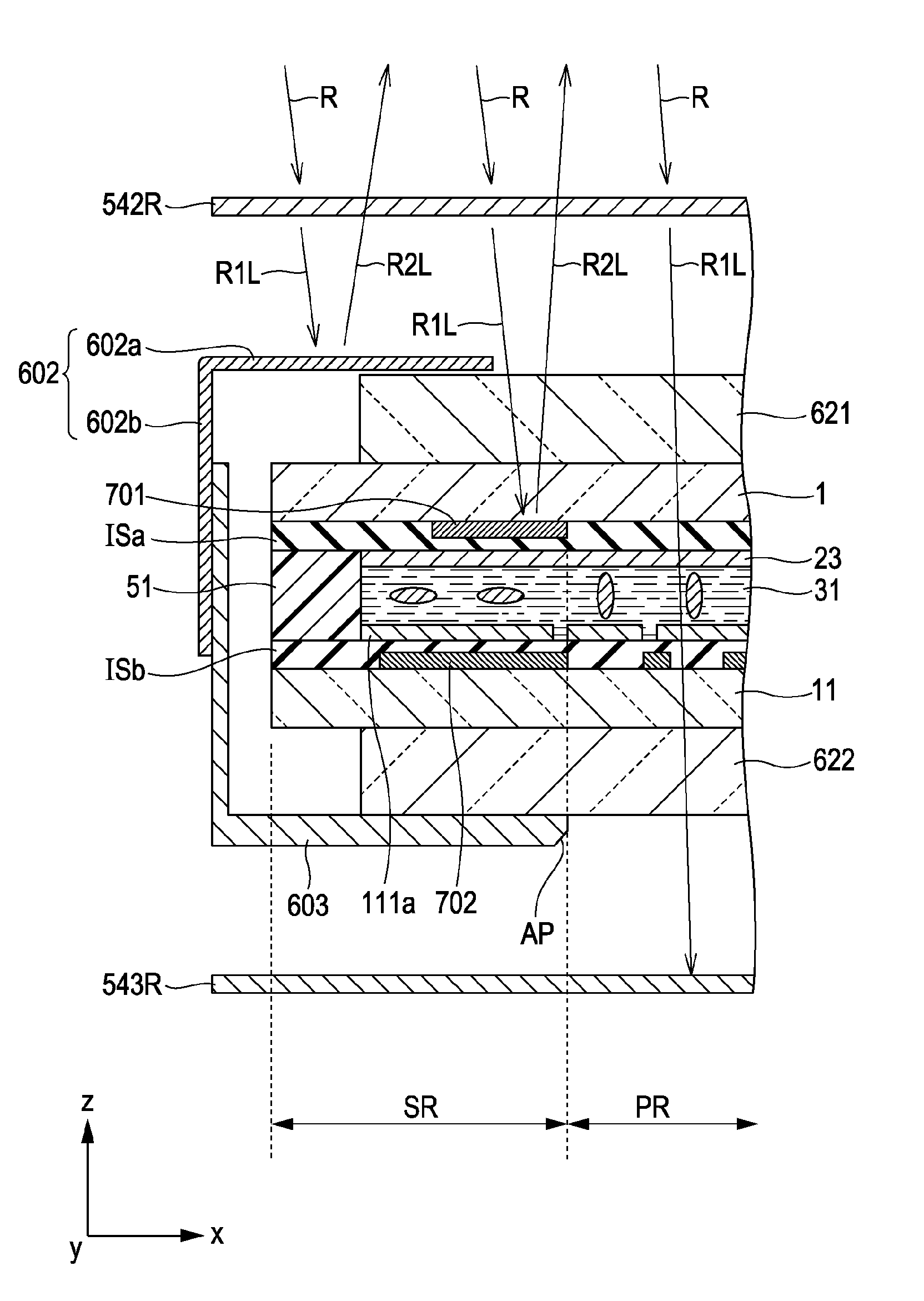
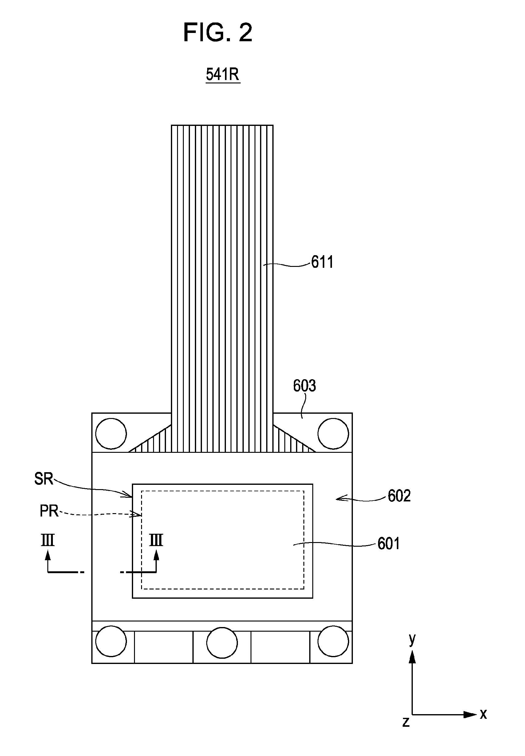
[0164]FIGS. 16 and 17 are illustrations showing a first LCD portion 541R according to a second embodiment of the present invention.

[0165]FIG. 16 is a plan view showing the first LCD portion 541R according to the second embodiment of the present invention. Also, FIG. 17 is a cross section showing the first LCD portion 541R according to the second embodiment of the present invention. FIG. 17 schematically illustrates a primary portion of the first LCD portion 541R, the cross section which is taken along line XVII-XVII in FIG. 16.

[0166]Referring to FIGS. 16 and 17, this embodiment is different from the first embodiment in that a light-shielding layer 703 is provided instead of the light-shielding plate 602. This embodiment is similar to the first embodiment except this point. Hence, description of similar configurations is omitted.

[0167]Referring to FIG. 17, the light-shielding layer 703 is provided on the surface of the first dustproof glass substrate 621 facing the liquid crystal pan...


PUM

PropertyMeasurementUnit
distanceaaaaaaaaaa
distanceaaaaaaaaaa
dielectric constantaaaaaaaaaa

Abstract

A light-shielding plate and a first light-shielding layer are arranged between a polarizing plate and a liquid crystal layer in a peripheral region of a liquid crystal panel so that linearly polarized light transmitted through the polarizing plate, which is a reflection polarizing plate, is not incident on the liquid crystal layer, but is reflected to the polarizing plate in the peripheral region.

Description

CROSS REFERENCES TO RELATED APPLICATIONS[0001]The present invention contains subject matter related to Japanese Patent Application JP 2007-229768 filed in the Japanese Patent Office on Sep. 5, 2007, the entire contents of which are incorporated herein by reference.BACKGROUND OF THE INVENTION[0002]1. Field of the Invention[0003]The present invention relates to liquid crystal display apparatuses and liquid crystal panels. In particular, the present invention relates to a liquid crystal display apparatus that uses a reflection polarizing plate as a polarizing plate, and in which light transmitted through the polarizing plate is incident on a pixel region of a liquid crystal panel to display an image. Also, the present invention relates to the liquid crystal panel used in the above-mentioned liquid crystal display apparatus.[0004]2. Description of the Related Art[0005]A liquid crystal display apparatus includes a liquid crystal panel in which a liquid crystal layer is sealed between a p...

Claims


Application Information

Patent Timeline
Patent Type & Authority Patents(United States)
IPC IPC(8): G02F1/1333G02F1/1335
CPCH04N9/3167G03B21/14G03B21/2073G02F1/1335
Inventor SHIRASAKA, YASUHIROOHMURA, KOHICHIKADOTA, HISASHITORIYAMA, AKIKOOKAZAKI, TSUYOSHI
Owner SONY CORP
Why Eureka
Try Eureka