Compressor turbine blade airfoil profile

a compressor turbine and blade technology, applied in the field of blade airfoil for gas turbine engines, can solve the problems of the total thrust or power capability of the engine, harsh temperatures for hp turbines, etc., and achieve the effect of reducing the trailing edge vortex and minimizing the disadvantage of flow separation

Active Publication Date: 2011-01-04
PRATT & WHITNEY CANADA CORP
View PDF8 Cites 6 Cited by
  • Summary
  • Abstract
  • Description
  • Claims
  • Application Information

AI Technical Summary

Benefits of technology

[0008]The profile shape of the present invention provides maximum work for a single stage high pressure turbine gas turbine engine, while minimizing flow separation disadvantages in such an environment. It is also necessary to give consideration to the downstream power turbine, to ensure that it can accept the flow conditions as they leave the HP turbine, without any adverse effect on the power turbine performance. The airfoil exit aerodynamic profile is suited for two-stage power turbine. The exit conditions of this HPT must be optimized such that the flow can negotiate the flow path in the inter turbine duct, and enter the LPT fully attached. To accomplish this, advanced 3D optimization techniques are used to ensure that the radial distribution of flow leaving the HPT lends itself to being able to negotiate the inter turbine duct shape without any flow separation. The airfoil tip section is optimized to reduce the trailing edge vortex going into the interturbine duct.

Problems solved by technology

Over and above this, the airfoil is subject to flow regimes which lend themselves easily to flow separation, which tend to limit the amount of work transferred to the compressor, and hence the total thrust or power capability of the engine.
The HP turbine is also subject to harsh temperatures and pressures, which require a solid balance between aerodynamic and structural optimization.

Method used


Image

  • Compressor turbine blade airfoil profile
  • Compressor turbine blade airfoil profile
  • Compressor turbine blade airfoil profile

Examples


Embodiment Construction

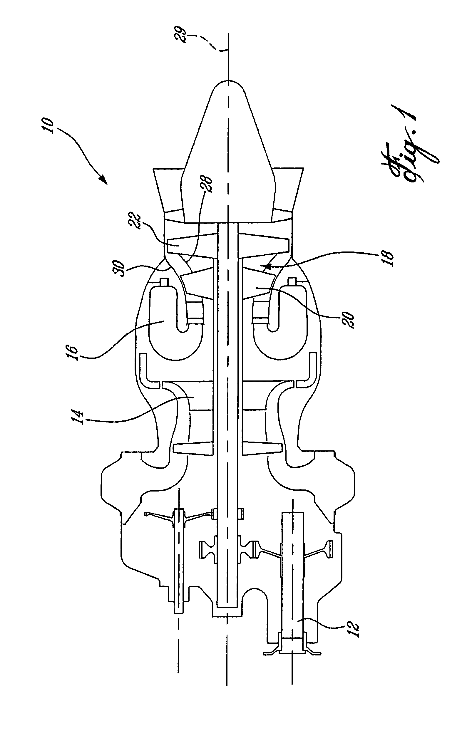
[0015]FIG. 1 illustrates a turboshaft engine 10 of a type preferably provided for use in subsonic flight, generally comprising in serial flow communication a centrifugal compressor 14 for pressurizing the air, a combustor 16 in which the compressed air is mixed with fuel and ignited for generating an annular stream of hot combustion gases, and a turbine section 18 for extracting energy from the combustion gases. The turbine section 18 comprises a single stage compressor turbine 20 and a two-stage power turbine 22. The compressor turbine 20 drives the compressor 14, whereas the power turbine drives the output shaft 12.

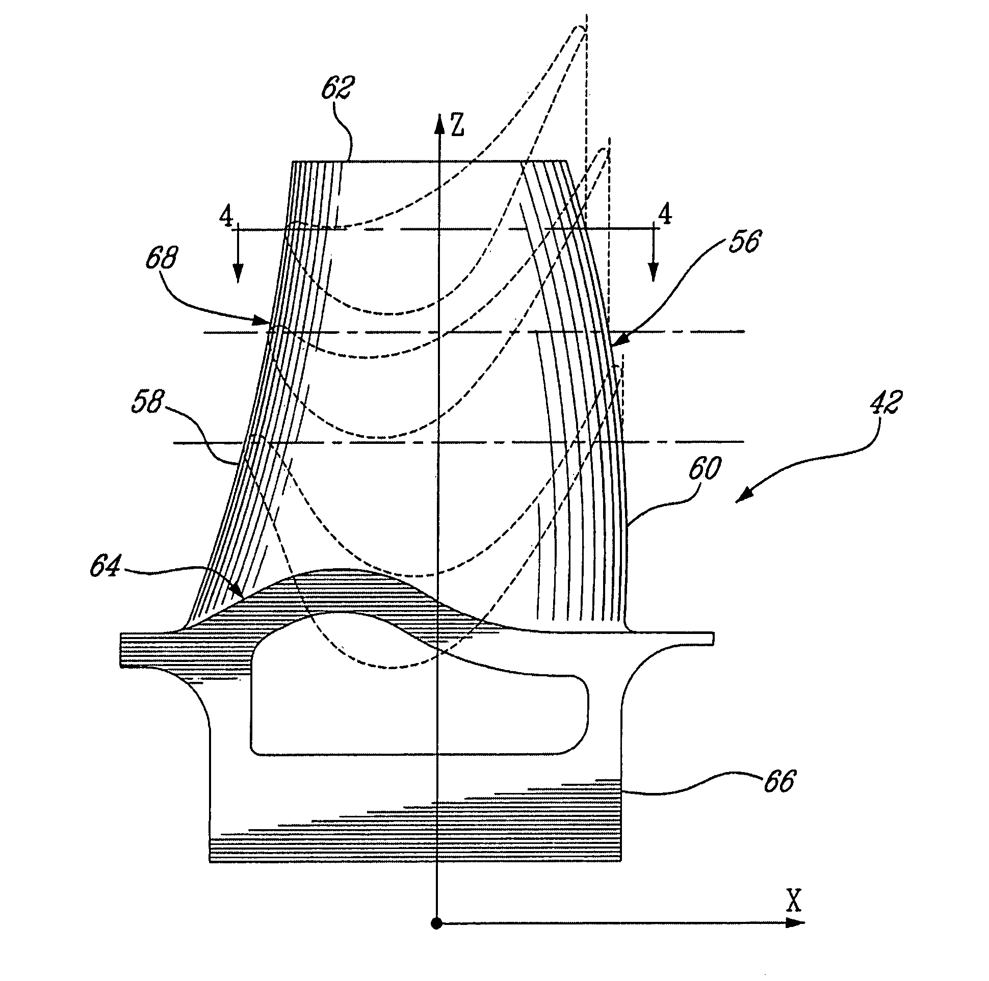
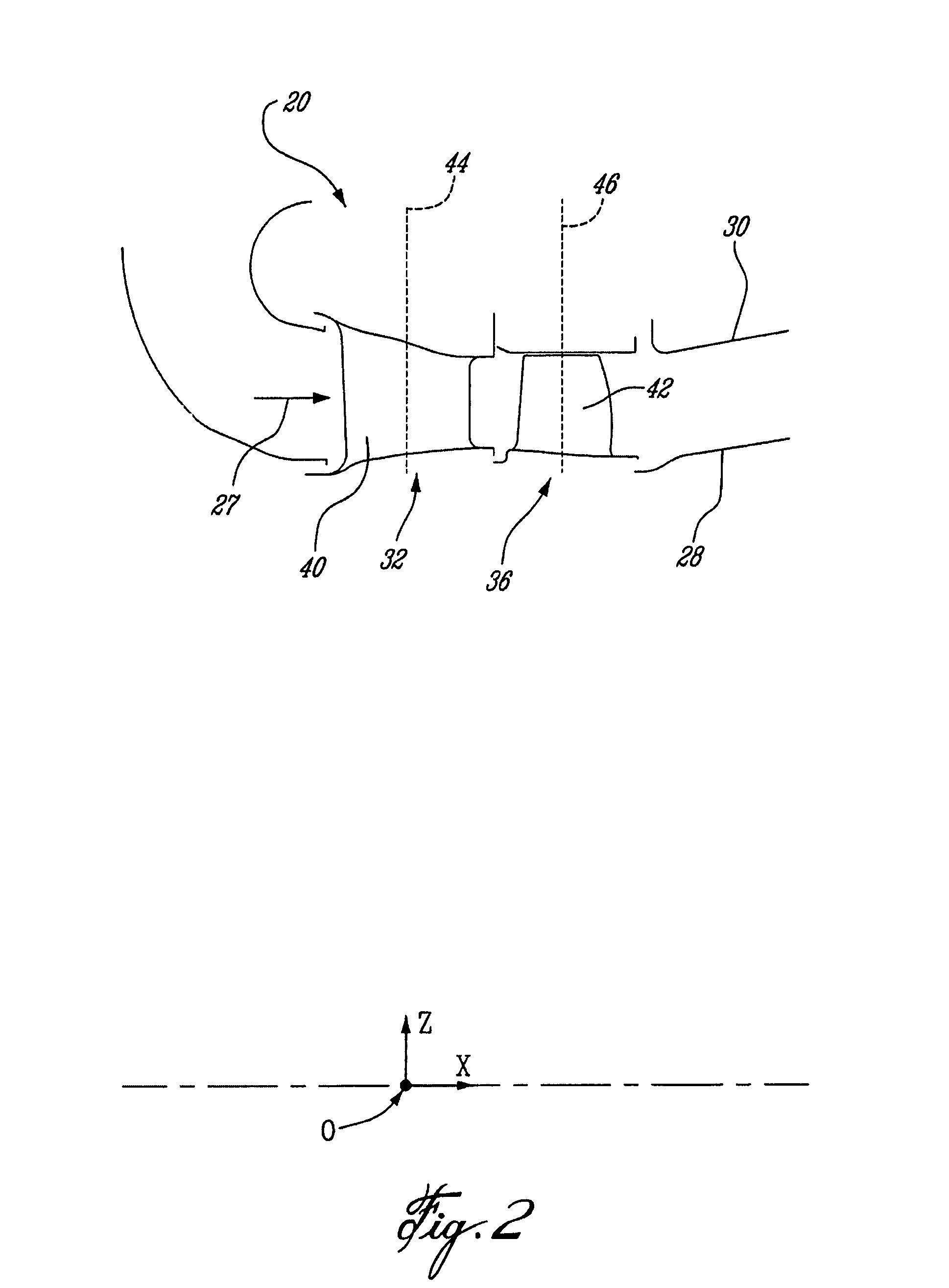
[0016]FIG. 2 illustrates a portion of an annular hot gaspath, indicated by arrows 27 and defined by annular inner and outer walls 28 and 30 respectively, for directing the stream of hot combustion gases axially in an annular flow. The profile of the inner and outer walls 28 and 30 of the annular gaspath, “cold” (i.e. non-operating) conditions, is defined by the Cartesia...


PUM


Abstract

A single stage high pressure turbine blade includes an airfoil having a profile substantially in accordance with at least an intermediate portion of the Cartesian coordinate values of X, Y and Z set forth in Table 2. The X and Y values are distances, which when smoothly connected by an appropriate continuing curve, define airfoil profile sections at each distance Z. The profile sections at each distance Z are joined smoothly to one another to form a complete airfoil shape.

Description

TECHNICAL FIELD[0001]The invention relates generally to a blade airfoil for a gas turbine engine and, more particularly, to an airfoil profile suited for a high pressure turbine (HPT) stage blade.BACKGROUND OF THE ART[0002]Where a blade airfoil is part of a single stage turbine driving a compressor (i.e. part of a high pressure or HP turbine), the requirements for such a blade airfoil design are significantly more stringent than multiple stage airfoil designs, as the compressor relies solely on this single stage HP turbine to deliver all the required work, as opposed to work being spread over several turbine stages. Over and above this, the airfoil is subject to flow regimes which lend themselves easily to flow separation, which tend to limit the amount of work transferred to the compressor, and hence the total thrust or power capability of the engine. The HP turbine is also subject to harsh temperatures and pressures, which require a solid balance between aerodynamic and structural...

Claims


Application Information

Patent Timeline
Patent Type & Authority Patents(United States)
IPC IPC(8): B64C27/46
CPCF01D5/141F01D5/143F05D2250/74F05D2220/321Y10S416/02
Inventor SAINDON, PIERREDION, MICHELGIRGIS, SAML
Owner PRATT & WHITNEY CANADA CORP
Why Eureka
Try Eureka