Fiber optic spectroscopic digital imaging sensor and method for flame properties monitoring

a fiber optic spectroscopic digital imaging and flame property technology, applied in the direction of optical radiation measurement, instruments, spectrometry/spectrophotometry/monochromators, etc., can solve the problems of difficult to obtain reliable measurements, limited control methods, and several challenges to measurement inside the combustor or gasification reactor vessel. achieve the effect of minimizing the impact of purging gas, wide observation angle and limiting effects

a fiber optic spectroscopic digital imaging and flame property technology, applied in the direction of optical radiation measurement, instruments, spectrometry/spectrophotometry/monochromators, etc., can solve the problems of difficult to obtain reliable measurements, limited control methods, and several challenges to measurement inside the combustor or gasification reactor vessel. achieve the effect of minimizing the impact of purging gas, wide observation angle and limiting effects

US7907272B2Active Publication Date: 2011-03-15THE BOARD OF TRUSTEES OF THE UNIV OF ILLINOIS

Image

  • Fiber optic spectroscopic digital imaging sensor and method for flame properties monitoring
  • Fiber optic spectroscopic digital imaging sensor and method for flame properties monitoring
  • Fiber optic spectroscopic digital imaging sensor and method for flame properties monitoring

Examples


Embodiment Construction

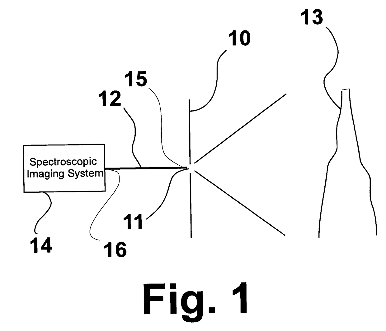
[0024]FIG. 1 is a schematic representation of the salient features of the system of this invention. As shown therein, the system comprises a wall 10 having a pinhole opening 11. Imaging fiber optic bundle 12 having a light receiving end 15 and a light output end 16 is disposed on one side of wall 10 with the flame 13 to be monitored disposed on the opposite side of wall 10. Light receiving end 15 of the imaging fiber optic bundle is aligned with pinhole opening 11. Pinhole opening 11 acts to focus the flame image received by the light receiving end of the fiber optic bundle. As used herein, the term “pinhole” refers to openings having a diameter in the range of about 1 μm to about 1 mm. In accordance with one particularly preferred embodiment of this invention, pinhole opening 11 has a diameter in the range of about 10 μm to about 100 μm. Unexpectedly, the use of a pinhole opening obviates the need for focusing lenses, protective windows, or any other object intervening between the ...


PUM


Abstract

A system for real-time monitoring of flame properties in combustors and gasifiers which includes an imaging fiber optic bundle having a light receiving end and a light output end and a spectroscopic imaging system operably connected with the light output end of the imaging fiber optic bundle. Focusing of the light received by the light receiving end of the imaging fiber optic bundle by a wall disposed between the light receiving end of the fiber optic bundle and a light source, which wall forms a pinhole opening aligned with the light receiving end.

Description

[0001]The U.S. Government has a paid-up license in this invention and the right in limited circumstances to require the patent owner to license others on reasonable terms as provided for by the terms of Contract No. DE-FC26-02NT41585 awarded by the U.S. Department of Energy.BACKGROUND OF THE INVENTION[0002]1. Field of the Invention[0003]This invention relates to a method and apparatus for monitoring the properties of flames in high pressure combustors and gasifiers in real time. More particularly, this invention relates to a sensor for real-time monitoring of flame properties using fiber optic spectroscopic digital imaging. Although intended for use in connection with pressurized combustors and gasifiers, the method and apparatus of this invention may be employed in any combustion apparatus in which slagging occurs or in which the environment of the combustion process is particle- and / or particulate-laden, i.e. a “dirty” or “dusty” environment, including processes at about atmospher...

Claims


Application Information

Patent Timeline
15 Mar 2011
Publication
US7907272B2
IPC
G01J3/28
CPC
G01J3/02; G01J3/0218; G01J3/0286; G01J3/2823; G01J5/0014; G01J5/0044; G01J5/02; G01J5/029
Inventors
ZELEPOUGA, SERGUEI A.; RUE, DAVID M.