Handling mechanism of trays with which electronic parts are fed and inspection device of the electronic parts using the mechanism

a technology of electronic parts and trays, which is applied in the direction of stacking articles, packaging goods, de-stacking articles, etc., can solve the problems of increasing the size of the device, unable to enhance the inspection efficiency of the magnetic head, etc., and achieves the reduction of the size of the inspection device of electronic parts and the exchange frequency of the trays.

Inactive Publication Date: 2011-04-05
HITACHI HIGH-TECH CORP
View PDF13 Cites 6 Cited by
  • Summary
  • Abstract
  • Description
  • Claims
  • Application Information

AI Technical Summary

Benefits of technology

[0012]An object of the present invention is to resolve such problems in the conventional art and to provide, when continuously inspecting electronic parts, for example, magnetic head assemblies (magnetic heads), a handling mechanism of trays for the electronic parts fed by the trays, in which an exchange frequency of the trays and a size for the device can be decreased, or an inspection device for the electronic parts using the mechanism.
[0019]As a result, through the re-use of the empty trays within the inspection device, a discharge process of the empty trays from the inspection device is unnecessitated. Moreover, the empty tray rack serving as an empty tray stocker is provided above the tray placing rack. Since an empty tray is fed to the empty tray rack via the first opening from the bottom thereof, the operation of a handling robot for placing the empty tray or stacking empty trays on the empty tray rack can be performed in a like operation when putting in and out of trays with respect to the tray placing rack. Thereby, a feeding and discharging of empty trays with respect to the empty tray rack can be performed with a simple control. Moreover, since the empty trays may be stored on the empty tray rack in a stacked manner as a tray stacking rack, an area required for storing the empty trays is reduced.
[0022]As a result, when continuously inspecting electronics parts, for example, magnetic head assemblies (magnetic heads), an exchange frequency of the trays is decreased while a size for the inspection device of electronic parts is also reduced.

Problems solved by technology

However, in this instance, when feeding and discharging of trays are delayed in time, of the throughput of magnetic head inspection is unable to be enhanced.
Further, since a system for feeding and discharging of many trays is needed, a problem arises of increasing the size of the device.

Method used


Image

  • Handling mechanism of trays with which electronic parts are fed and inspection device of the electronic parts using the mechanism
  • Handling mechanism of trays with which electronic parts are fed and inspection device of the electronic parts using the mechanism
  • Handling mechanism of trays with which electronic parts are fed and inspection device of the electronic parts using the mechanism

Examples


Embodiment Construction

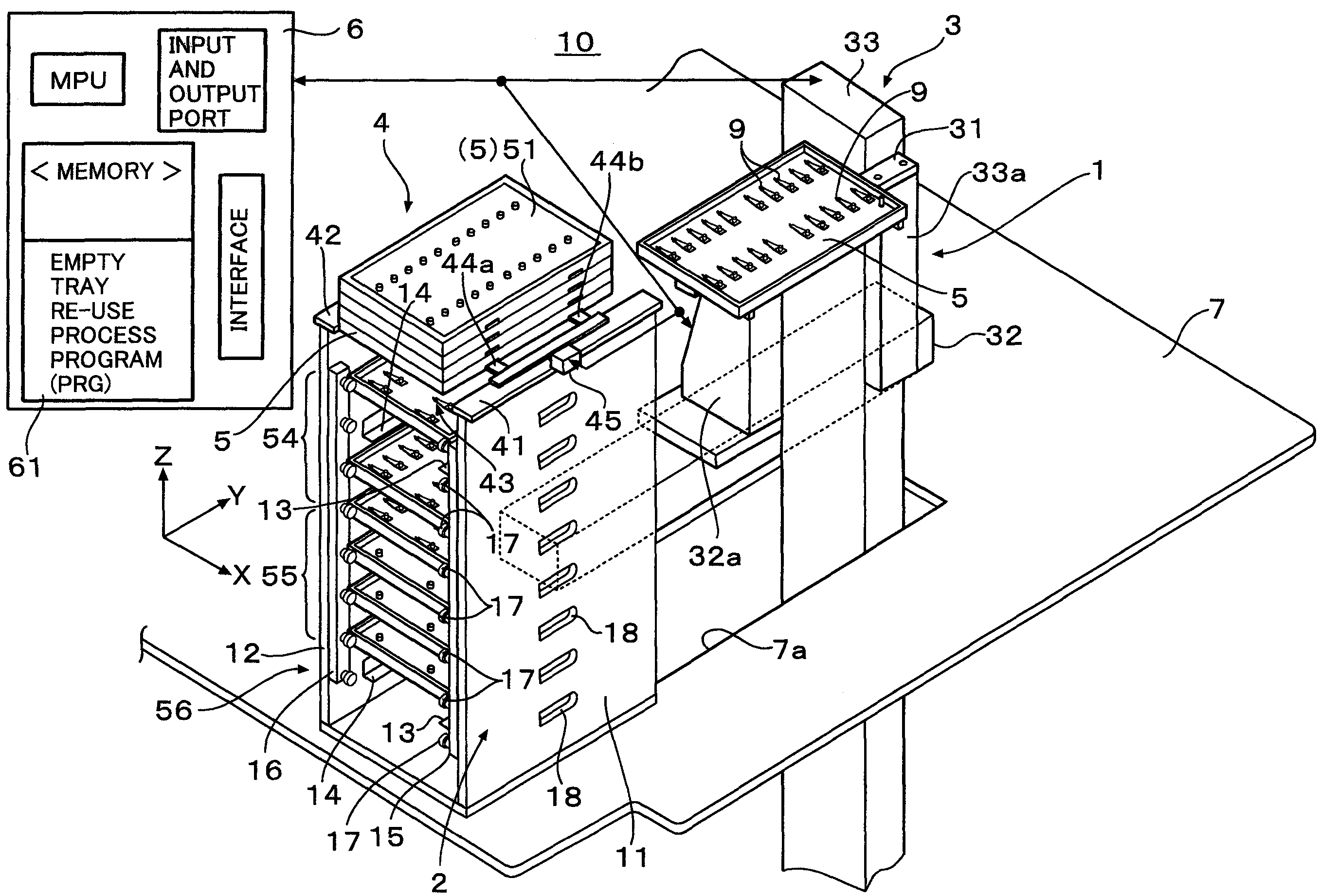
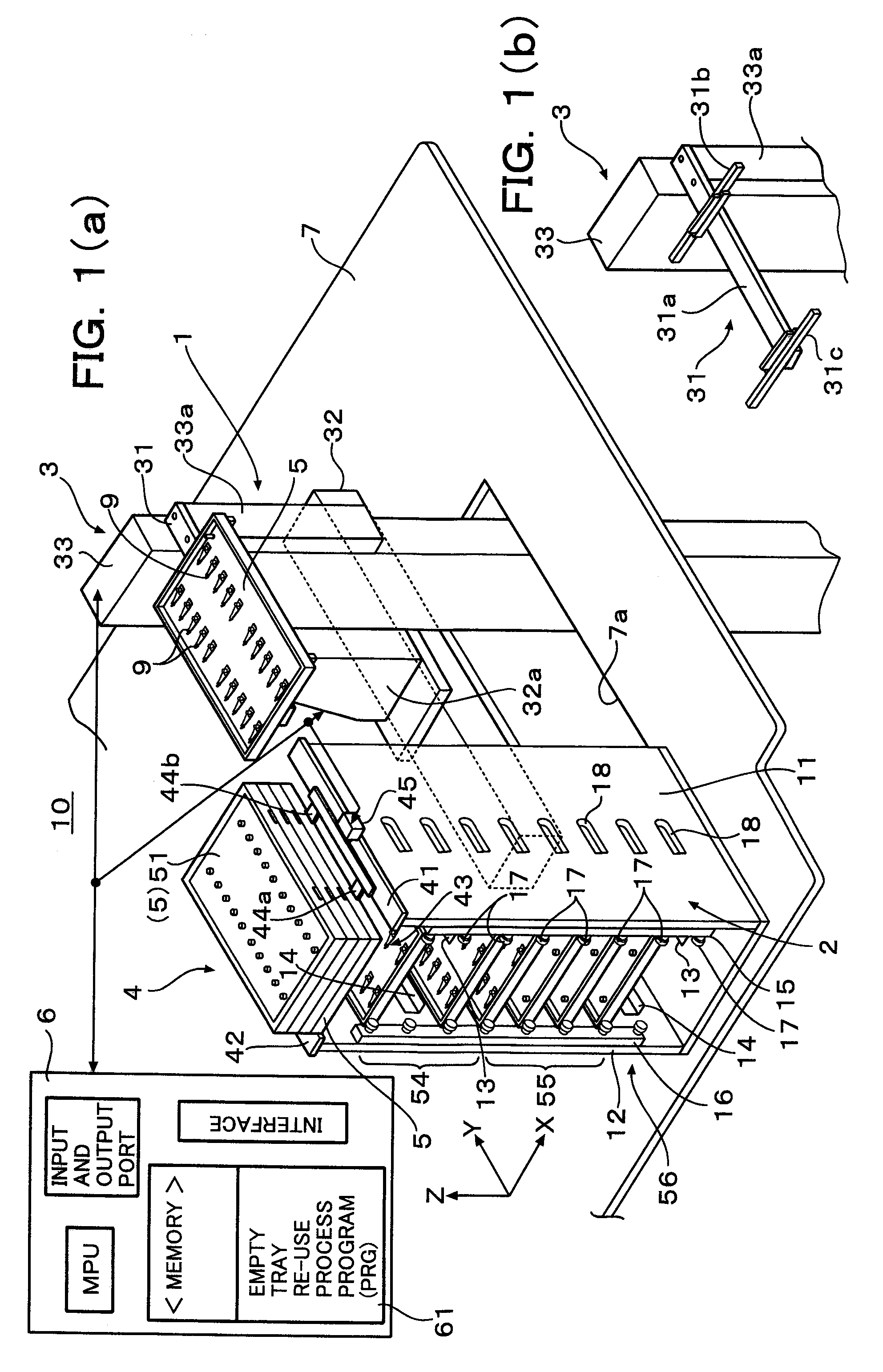
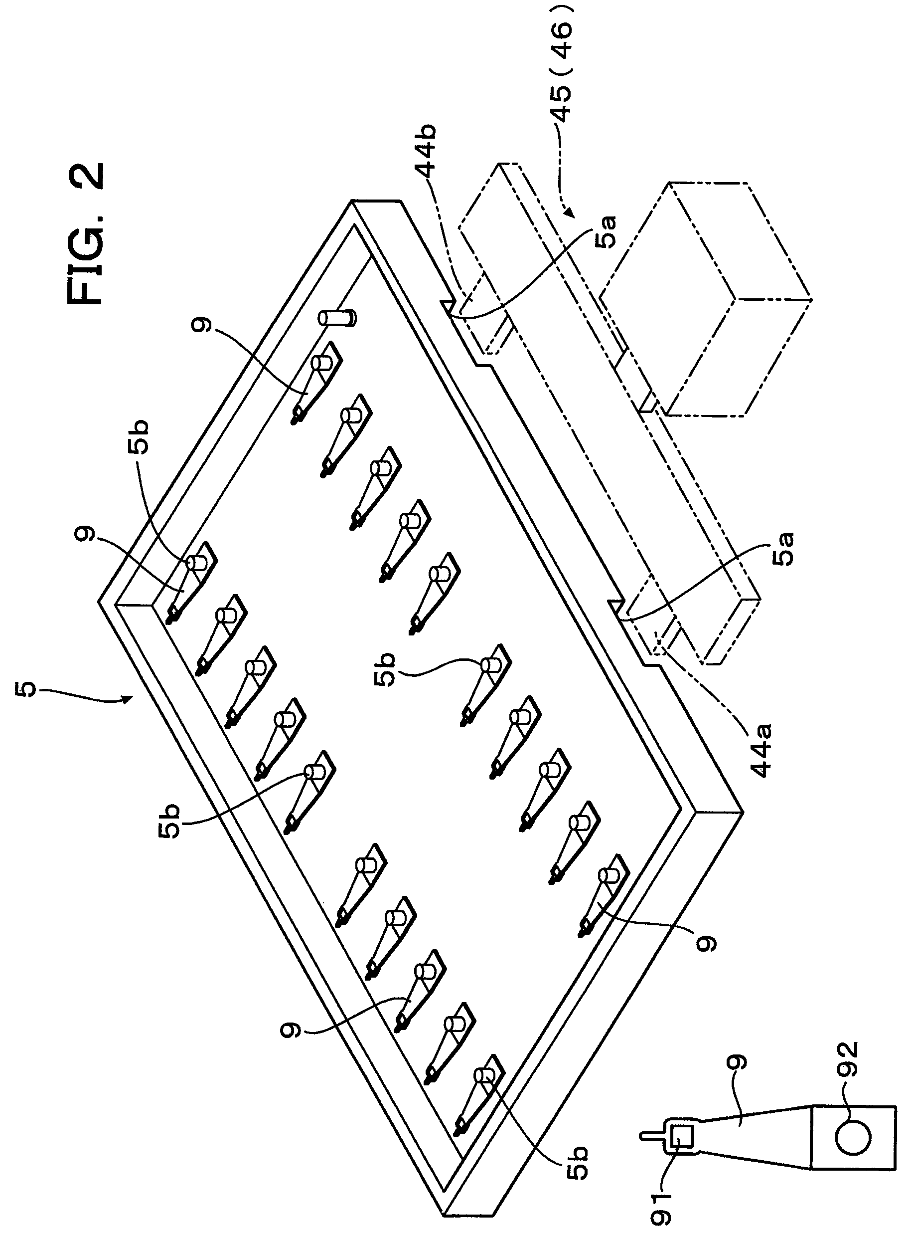
[0029]In FIG. 1 (a), numeral 10 is a magnetic head inspection device, 1 is a tray handling mechanism, 2 is a tray placing rack for storing trays in multi steps, 3 is a tray handling robot, 4 is a tray stacking rack, 5 is a box type rectangular tray for accommodating many magnetic head assemblies in array, 6 is a control unit, 7 is a mounting base for securing the tray placing rack 2, 8 is a magnetic head assembly handling robot (not shown in FIG. 1, see FIG. 5 and herein after will be called as a head handling robot) and 9 is magnetic head assemblies.

[0030]The control unit 6 includes therein such as an MPU, a memory, an input and output port and an interface and performs a variety of controls when the MPU executes programs stored in the memory. In the memory a PRG (program) 61 for an empty tray re-use process is stored which will be explained later.

[0031]The tray placing rack 2 is provided with racks of 8 steps of which front face is arranged so as to run along X axis under a condit...


PUM


Abstract

In the present invention, through the provision of a tray placing rack for storing trays in multi steps, the trays accommodating electronic parts after inspection are received in the racks and through the provision of a tray stacking rack above the tray placing rack, an empty tray emptied by having been inspected of the electronic parts before inspection at an inspection stage is stacked on the tray stacking rack. When a certain tray is filled with electronic parts after inspection and is discharged, an empty ray is taken out from the tray stacking rack and the empty tray is fed to the rack position of the discharged tray to permit re-use of empty trays.

Description

FIELD OF THE INVENTION[0001]The present invention relates to a handling mechanism of trays with which electronic parts are fed and an inspection device of the electronic parts using the mechanism, and more specifically relates, when many magnetic head assemblies (a magnetic head+a suspension spring) arranged and accommodated in a tray are fed to an inspection stage via the tray to continuously inspect the magnetic head assemblies, to a handling mechanism of trays for the magnetic head assemblies fed by the trays, in which an exchange frequency of the trays is decreased as well as a size for the device can be reduced.BACKGROUND ART[0002]Recently, an increase in the recording density of magnetic discs has accelerated and presently, hard disc drive devices (HDD) which have a capacity on an order of several hundreds gigabytes have become mainstream. Due to the increases in the recording density in magnetic discs, a floating amount of each magnetic disc lowers.[0003]In a recent magnetic ...

Claims


Application Information

Patent Timeline
Patent Type & Authority Patents(United States)
IPC IPC(8): B65G59/06B65G57/30
CPCG11B5/455
Inventor SUGIYAMA, TOSHINORITOKUMURA, YOSHINORITSUYUKI, SYOJISUZUKI, TOSHIAKIKAWAMOTO, SHINJI
Owner HITACHI HIGH-TECH CORP
Why Eureka
Try Eureka