

Distance measuring device and distance measuring method
a technology of distance measurement and distance measurement, which is applied in the direction of measurement devices, using reradiation, instruments, etc., can solve the problems of difficult to achieve a simple construction, lack of tens of meters, and difficulty in measuring the close range within several tens of meters, etc., to achieve simple construction, low cost, and small size
- Summary
- Abstract
- Description
- Claims
- Application Information
AI Technical Summary
Benefits of technology
Problems solved by technology
Method used
Image

Examples
first embodiment
[0116]A technical outline of the first embodiment of the distance measuring device and the distance measuring method related to the claimed invention will be described as follows.
[0117](Technical Outline 1)
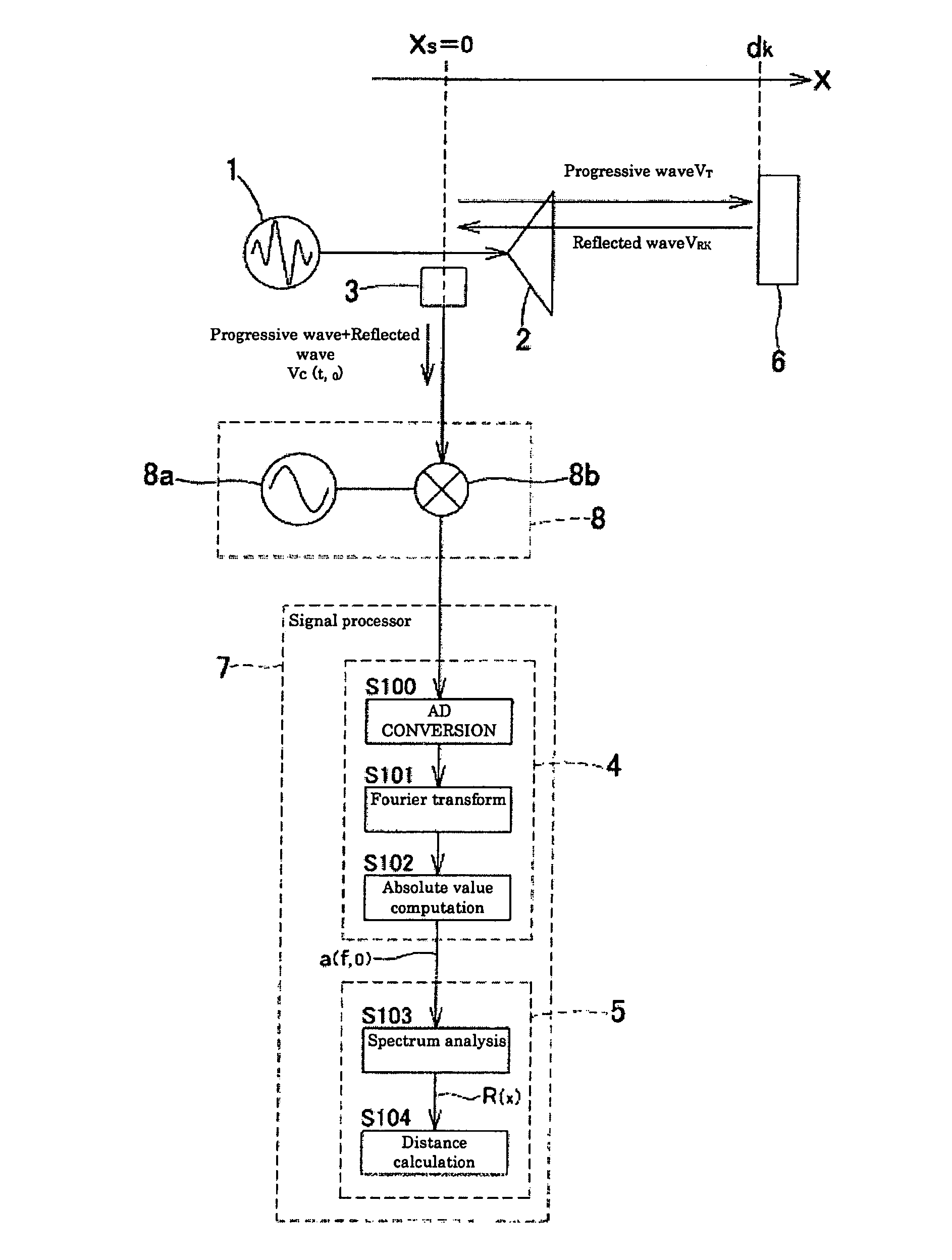
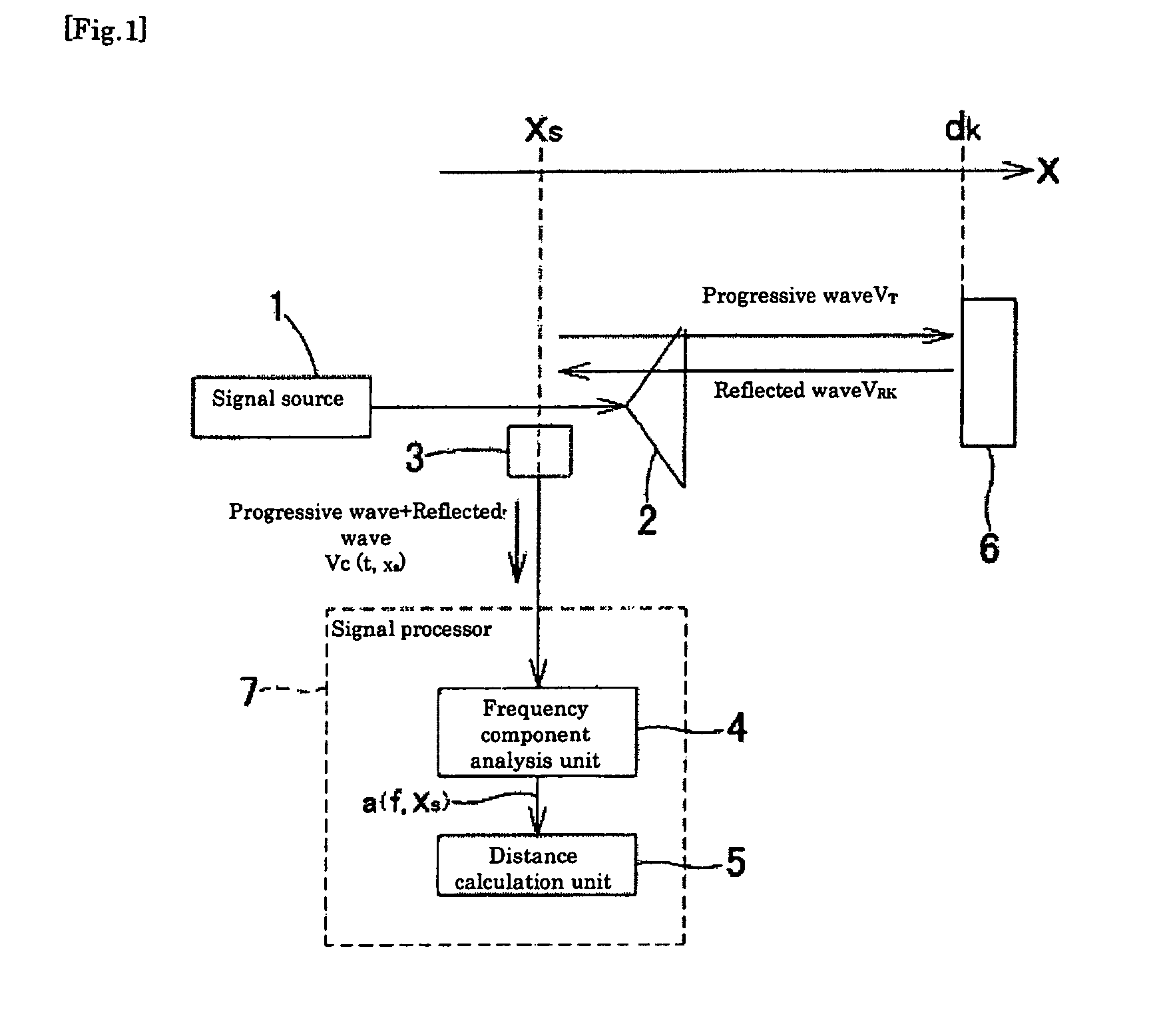
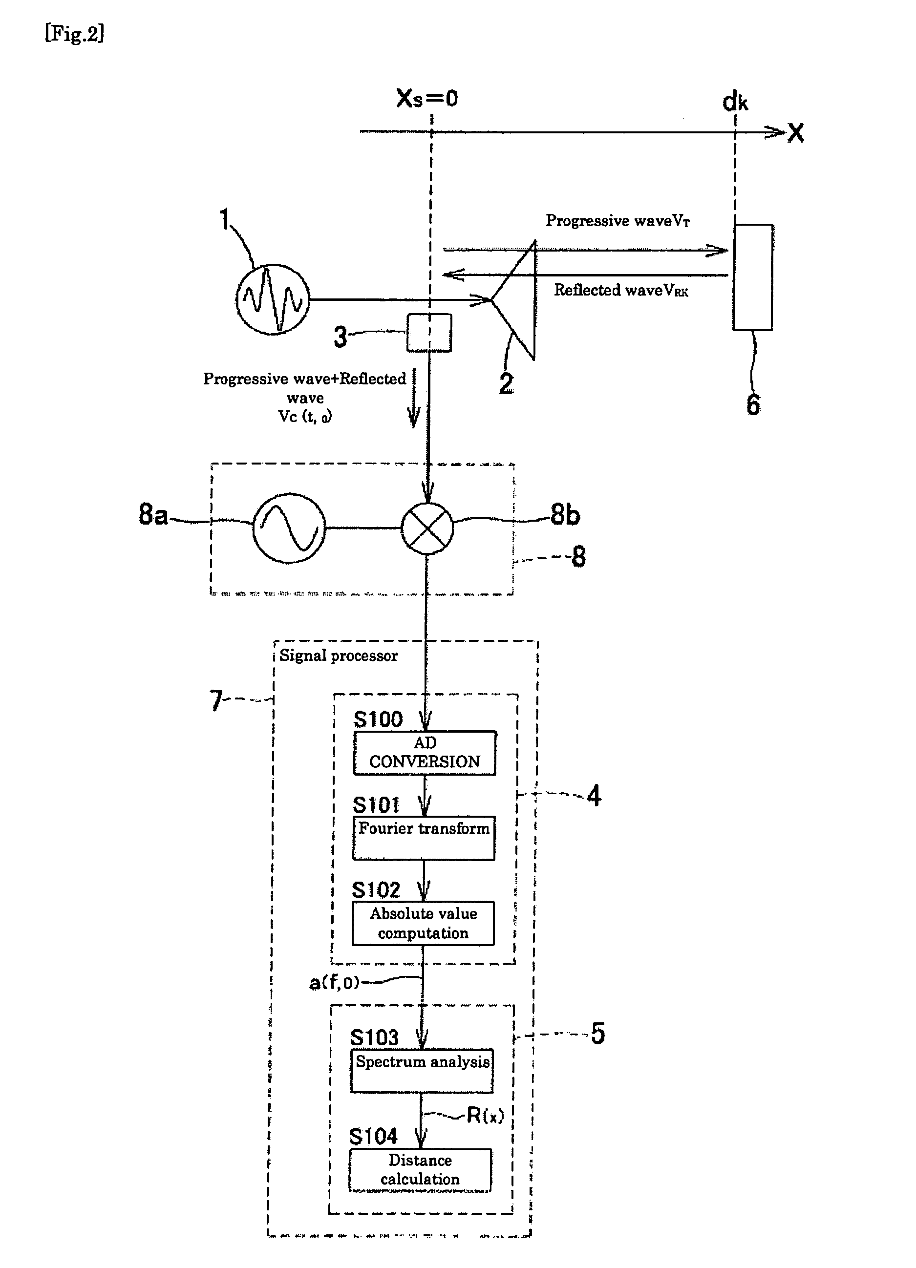
[0118]FIG. 1 is an illustration that explains the outline of a distance measuring device related to the claimed invention. The distance measuring device related to the claimed invention transmits a signal (progressive wave VT) outputted from a signal source 1 as an undulation from a transmission unit 2 to a measurement object 6, detects a mixed wave VC of a reflected wave VRk reflected by the kth measurement object 6 and the progressive wave VT at a mixed wave detection unit 3, analyzes a frequency component (a(f, xs)) of the mixed wave at a frequency component analysis unit 4, calculates a distance spectrum R(x) at a distance calculation unit 5, and measures the distance to the measurement object 6.
[0119]The signal source 1 outputs a signal having a plurality of different frequen...
second embodiment
[0175]A technical outline of the second embodiment of the distance measuring device and the distance measuring method related to the claimed invention will be described as follows.
[0176](Technical Outline 2)
[0177]FIG. 8 is an illustration that explains the outline of a distance measuring device related to the claimed invention. The distance measuring device related to the claimed invention transmits a signal outputted from a signal source 9 as an undulation from a transmission unit 2 to a measurement object 6, detects a mixed wave VC of a reflected wave VRk reflected by the kth measurement object 6 and the progressive wave VT at a mixed wave detection unit 3, detects an amplitude component (a(t, xs) of the mixed wave at an amplitude component detection unit 10, calculates a distance spectrum R(x) at a distance calculation unit 11, and measures the distance to the measurement object 6.
[0178]The signal source 9 outputs a frequency-modulated signal obtained by frequency-modulating a ca...
third embodiment
[0228]A technical outline of the third embodiment of the distance measuring device and the distance measuring method related to the claimed invention will be described as follows.
[0229](Technical Outline 3)
[0230]FIG. 15 is an illustration that explains the outline of a distance measuring device related to the claimed invention. The distance measuring device related to the claimed invention transmits a signal outputted from a signal source 13 as an undulation from a transmission unit 2 to a measurement object 6, detects a mixed wave VC of a reflected wave VRk reflected by the kth measurement object 6 and a progressive wave VT at a mixed wave detection unit 3, processes this mixed wave VC with a signal processor 14, and finds the distance to the measurement object 6. The signal processor 14 comprises an amplitude component detection unit 15, single frequency selection unit 16, signal level detection unit 17, and distance calculation unit 18, and an amplitude component (a(t, xs)) of th...
PUM
 Abstract
Description
Claims
Application Information