Lens for LED outdoor lamp, and its applied road lamp, security lamp, tunnel lamp, park lamp, guard lamp, industrial flood lamp, and outdoor lamp

a technology of led outdoor lamps and led lamps, which is applied in the direction of instruments, lighting and heating apparatus, semiconductor devices for light sources, etc., can solve the problems of environmental pollution, large electric consumption of lamps, and short life, so as to reduce optical energy loss, improve radiation efficiency, and prevent light pollution

Inactive Publication Date: 2011-08-30
YUYANG D&U CO LTD
View PDF4 Cites 16 Cited by
  • Summary
  • Abstract
  • Description
  • Claims
  • Application Information

AI Technical Summary

Benefits of technology

[0008]One embodiment of the present invention provides a lens for an LED outdoor lamp, which has a superior effect regarding light concentration so that the lens is suitable for conditions regarding light distribution, brightness, and energy saving when the lens is used in the road lamps, security lamps, tunnel lamps, park lamps, guard lamps, industrial flood lamps, and outdoor lamps, the present invention also providing these lamps without glare and radiation lights, in which superior brightness and uniformity are secured, an illumination range is accurate, and energy can be remarkably saved.
[0019]According to yet another embodiment of the invention, when the lens is used, a distribution curve of luminous intensity is shaped like a wing of a bat, and the section of the lens can be changed as needed. Therefore, distribution of light can be reasonably adjusted so as to form the shape of a light field of the lighting device into a square shape. Also, it is possible to increase radiation efficiency to more than 75% and increase a total projection rate to more than 90% so that loss of optical energy is reduced at the maximum degree and light emitted from an optical source can be used well.
[0020]Moreover, there is an advantage in that brightness within an available illumination range of the lighting device is very uniform, and the edge of the light field is clear so that stray light hardly exists outside of the available illumination range, and also glare doesn't occur, thereby preventing pollution of light. Therefore, the present disclosure provides energy-saving green purity lighting, which can be applied to illumination fields, such as road illumination, lighting for advertisements, etc., which require special conditions.

Problems solved by technology

Such lamps require large electric consumption and have a short life.
Also, they require high maintenance and repair costs and may cause environmental contamination.
However, a light field obtained by projecting light through the conventional circular lens has a circular shape, and there is a big difference in brightness between the central part of the light field and the peripheral part thereof.
However, in that case, light fields are overlapped with each other so that brightness is higher, but the distribution of lighting intensity is not uniform.
Due to such a lighting phenomenon, the area under lighting devices has high brightness, but other areas have low brightness so that the average brightness of the road is low and is not uniform.
As a result, there is much probability that a driver sees an illusion while driving his / her car which can lead to a traffic accident, and also seriously influences safety in driving a vehicle.
Also, besides traffic roads, there is a problem that surroundings are polluted due to stray lights, and glare occurs in various outdoor / indoor environments.

Method used


Image

  • Lens for LED outdoor lamp, and its applied road lamp, security lamp, tunnel lamp, park lamp, guard lamp, industrial flood lamp, and outdoor lamp
  • Lens for LED outdoor lamp, and its applied road lamp, security lamp, tunnel lamp, park lamp, guard lamp, industrial flood lamp, and outdoor lamp
  • Lens for LED outdoor lamp, and its applied road lamp, security lamp, tunnel lamp, park lamp, guard lamp, industrial flood lamp, and outdoor lamp

Examples


second embodiment

[0046]FIG. 9 is a view showing a lighting device according to the present disclosure.

[0047]FIG. 10 is an exploded perspective view of a light module of the lighting device according to the embodiment of the present disclosure, and FIG. 11 is a perspective view of a lens cover of the lighting device according to the embodiment of the present disclosure. FIG. 12 is a plan view of the lens cover of the lighting device according to the embodiment of the present disclosure, and FIG. 13 is a view of a sectional view taken along line C-C′ of FIG. 12.

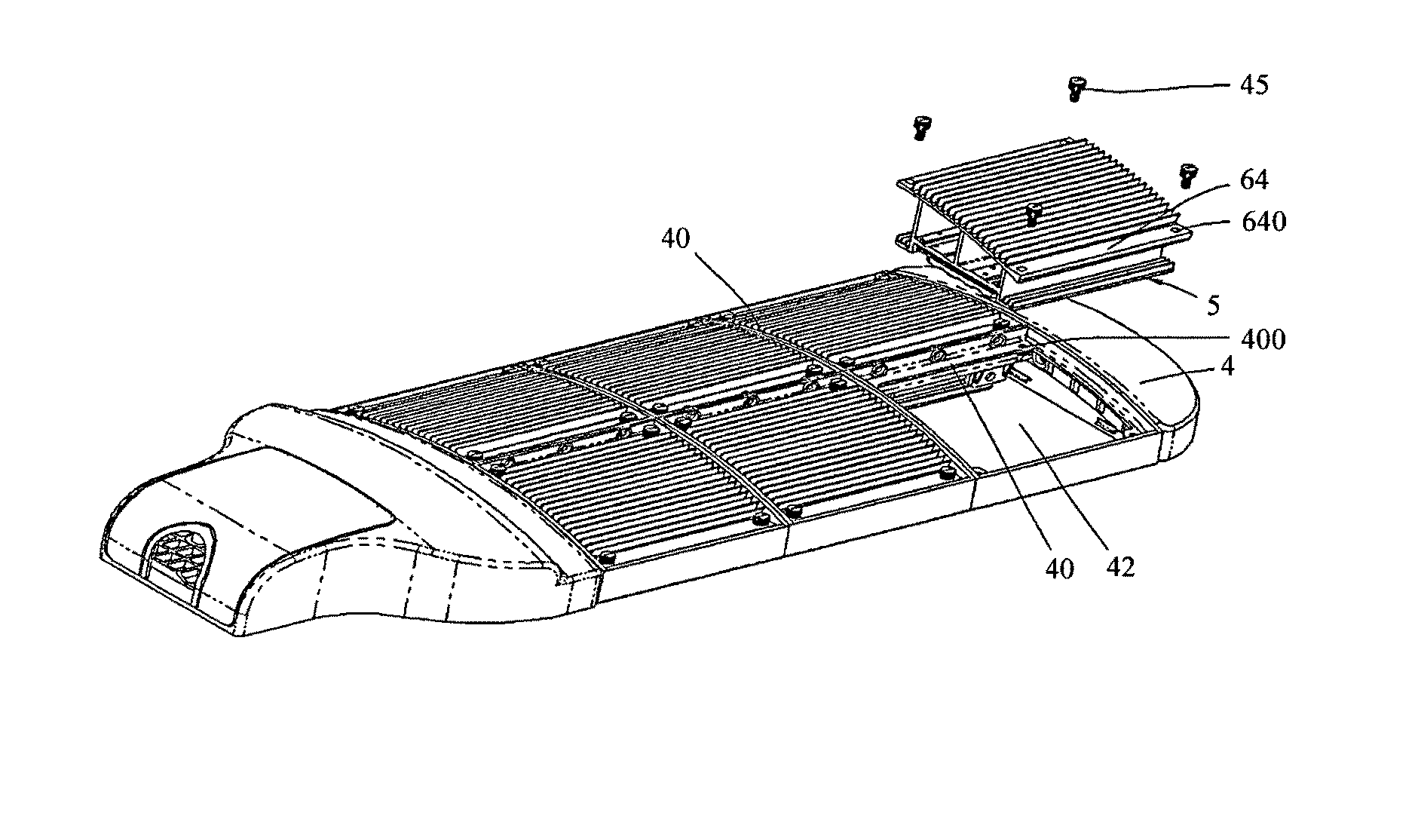
[0048]As shown in FIGS. 9 to 13, the lighting device according to the embodiment of the present disclosure includes at least one illumination module 5 and at least one frame 4 in which at least one illumination module 5 is installed.

[0049]Herein, the illumination module 5 includes a cooling part 6, a substrate 7 having an LED matrix, a printed circuit board or PCB 8, and a lens cover 9 having a lens matrix.

first embodiment

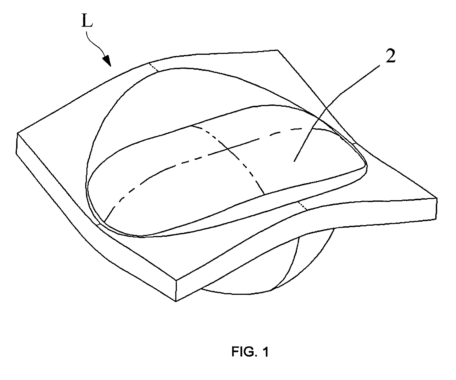
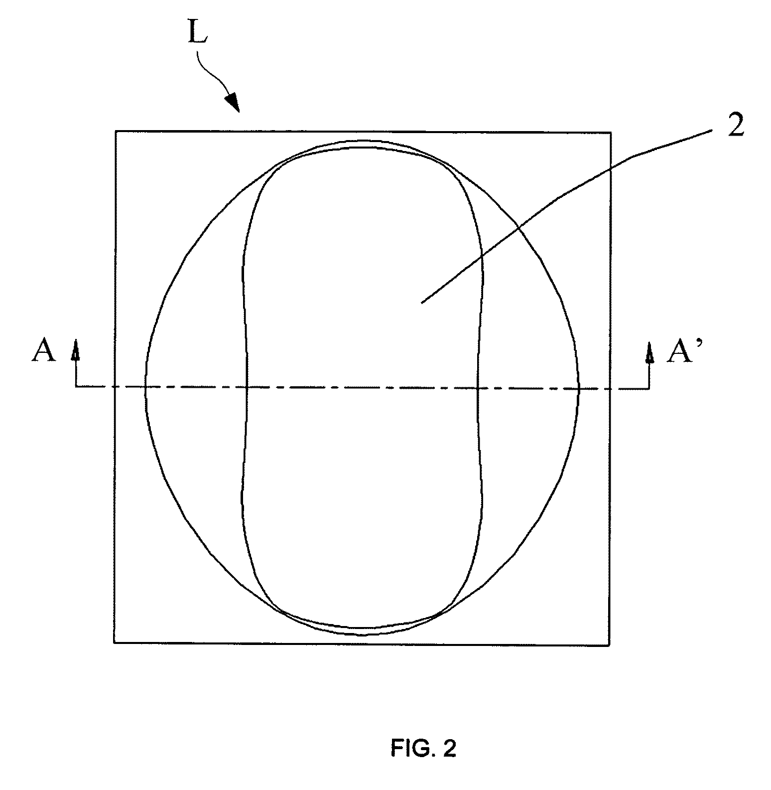
[0050]The substrate 7 is attached to a bottom surface of an upper part of the cooling part 6 through a thermal conductive insulation pad 71. The PCB 8 is installed at one side of the substrate 7, on which the LED matrix is disposed. A through-hole matrix formed by arranging a plurality of PCB through-holes 80 is included in the PCB 8. Each PCB through-hole 80 corresponds to each LED of the LED matrix one to one so as to allow each LED 70 of the LED matrix to pass through the corresponding PCB through-hole 80. The circuit of the PCB 8 is connected to each LED terminal. The structure of a single lens 90 in the lens matrix of the lens cover 9 is the same as that of the LED outdoor lamp lens according to the present disclosure. Therefore, the description of that will be omitted.

[0051]A plurality of cooling fins 60 is installed in the cooling part 6. A recess 62 is formed on a bottom surface of an upper part of the cooling part 6. The substrate 7 is installed on a bottom of the recess 62...


PUM


Abstract

Disclosed is a lens for an LED outdoor lamp, and a road lamp, a security lamp, a tunnel lamp, a park lamp, a guard lamp, an industrial flood lamp, and an outdoor lamp using the lens. There is an advantage in that the shape of a light field can be a square shape by controlling light distribution. Brightness is very uniform within a available illumination range, and stray light is hardly generated outside of the range.

Description

CROSS-REFERENCE TO RELATED APPLICATION[0001]This non-provisional application claims priority under 35 U.S.C §119(a) on Patent Application No. 10-2008-0093336 filed in Korea on Sep. 23, 2008, the entire contents of which are hereby incorporated by reference.TECHNICAL FIELD[0002]The present invention relates to a lens for Light Emitting Diode (LED) outdoor lamp, and its applied road lamp, security lamp, tunnel lamp, park lamp, guard lamp, industrial flood lamp, and outdoor lamp. More particularly, the present invention relates to a lens for an LED outdoor lamp, which secures uniform light within an effective illumination range and reduces quantity of light shining outside of the illumination range, that is, allows stray light to be nearly eliminated, and also to the road lamp, security lamp, tunnel lamp, park lamp, guard lamp, industrial flood lamp, and outdoor lamp using the LED lens.BACKGROUND OF THE DISCLOSURE[0003]Conventionally, for lighting city streets, natrium lamps, mercury l...

Claims


Application Information

Patent Timeline
Patent Type & Authority Patents(United States)
IPC IPC(8): F21V5/00
CPCF21V5/04G02B19/0066G02B19/0028F21W2131/10F21W2131/101F21W2131/103F21Y2101/02Y02B20/72F21V5/007F21V31/005F21Y2115/10F21K9/69F21Y2105/16
Inventor KIM, SANG-OKKIM, BYUNG-OHCHO, MIN-JIN
Owner YUYANG D&U CO LTD
Why Eureka
Try Eureka