Light guide plate and light source apparatus

Inactive Publication Date: 2011-09-22
YOUNG LIGHTING TECHNOLOGY INC
View PDF10 Cites 2 Cited by
  • Summary
  • Abstract
  • Description
  • Claims
  • Application Information

AI Technical Summary

Benefits of technology

[0009]Accordingly, the invention is directed t

Problems solved by technology

Since the radiation pattern of emitting-light of most LGPs is unable to be effectively controlled and most ones of them are emitting-light with half floodlight radiation pattern, so that a glare is caused in the lighting apparatus application, and the glare makes the

Method used


Image

  • Light guide plate and light source apparatus
  • Light guide plate and light source apparatus
  • Light guide plate and light source apparatus

Examples


first embodiment

The First Embodiment

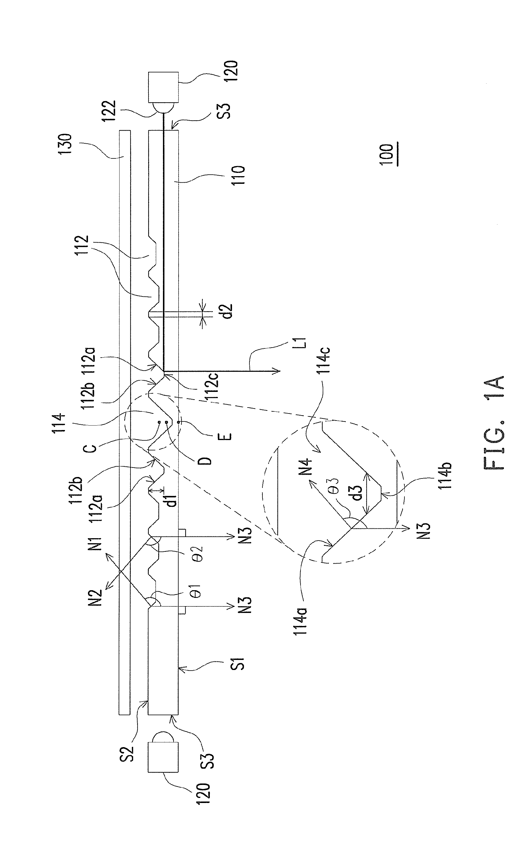
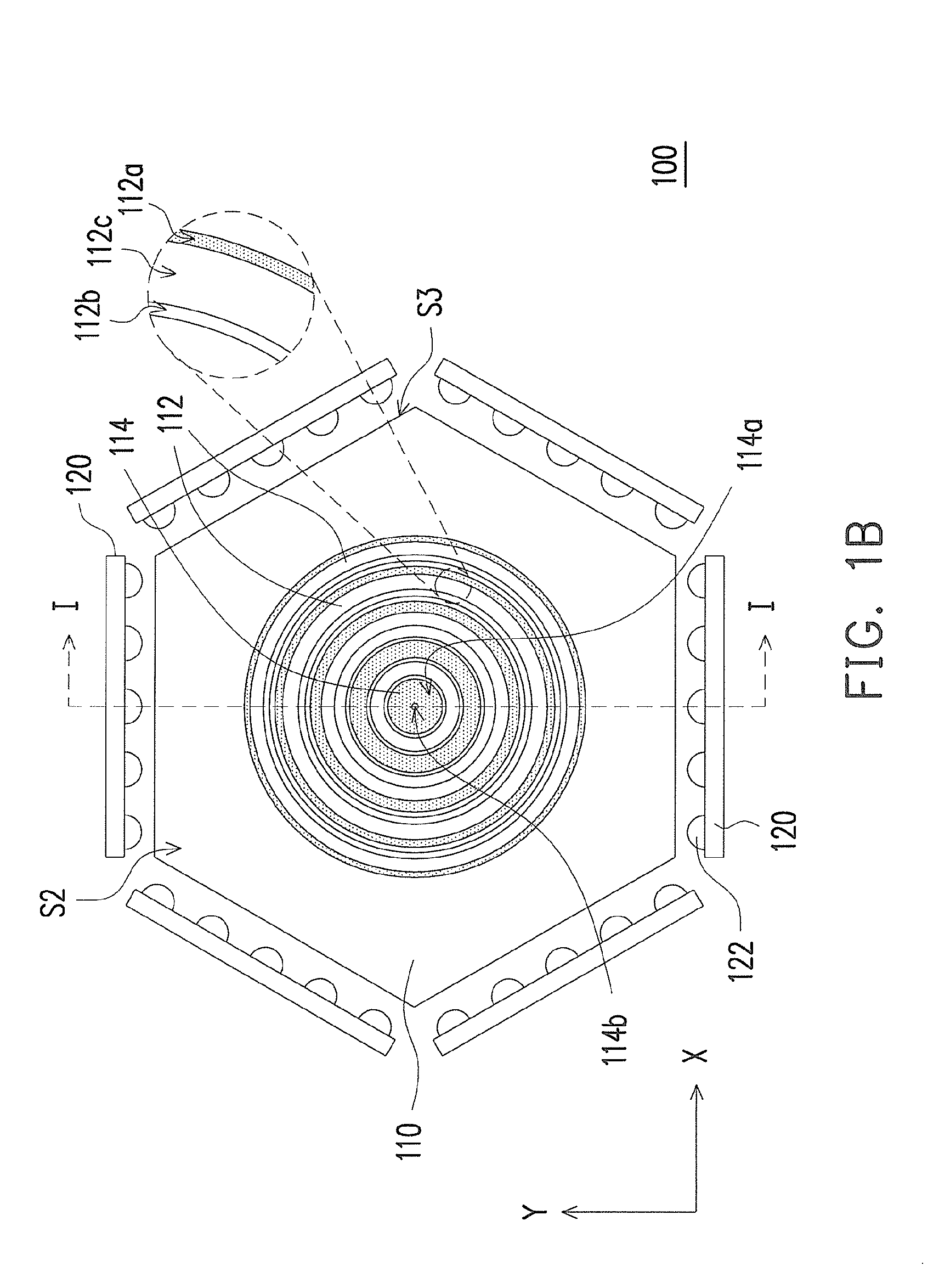
[0025]FIG. 1A is a sectional diagram of a light source apparatus according to the first embodiment of the invention and FIG. 1B is a top view diagram of the light source apparatus of FIG. 1A after removing the reflection sheet thereof, wherein FIG. 1A is a sectional diagram of FIG. 1B along I-I line. Referring to FIGS. 1A and 1B, a light source apparatus 100 includes an LGP 110 and a plurality of light-emitting units 120. The LGP 110 includes a first surface S1, a second surface S2, and a plurality of light incident surfaces S3. The second surface S2 is opposite to the first surface S1, wherein the first surface S1 is a light-emitting surface. The light incident surfaces S3 are connected to the first surface S1 and the second surface S2.

[0026]The light-emitting units 120 are respectively disposed beside the light incident surfaces S3, wherein each of the light-emitting units 120 is capable of emitting a light beam L1. The light beams L1 are capable of entering th...

second embodiment

The Second Embodiment

[0033]FIG. 4 is a top view diagram of a light source apparatus 200 according to the second embodiment of the invention. The light source apparatus 200 is similar to the light source apparatus 100 of FIG. 1B except that the ring-shaped groove 212 of the light source apparatus 200 is a polygon ring, for example, a pentagon ring. In addition, the shape of the LGP 210 may be designed as a pentagon LGP in association with the shape of the ring-shaped groove 212. Other depiction and modification related to the light source apparatus 200 may refer the first embodiment, which is omitted to describe.

third embodiment

The Third Embodiment

[0034]FIG. 5 is a sectional diagram of a light source apparatus 300 according to the third embodiment of the invention. The light source apparatus 300 is similar to the light source apparatus 100 of FIG. 1A except that the ring-shaped groove 312 of the light source apparatus 300 is a groove with triangle-shaped section, the cavity 314 is a triangle pyramid cavity. In other embodiments, the cavity 314 may also be a cone cavity. Other depiction and modification related to the light source apparatus 300 may refer the first embodiment, which is omitted to describe.

[0035]In summary, the embodiments of the invention include at least one of the following advantages or effects. In the embodiments of the invention, since the LGP has a plurality of light incident surfaces and a plurality of ring-shaped grooves, the emitting angle of the light beam may be effectively controlled so as to provide good light-emitting effect.


PUM


Abstract

A light guide plate (LGP) includes a first surface, a second surface, and a plurality of light incident surfaces. The first surface is a light-emitting surface. The light incident surfaces connect the first surface and the second surface. The second surface has a plurality of ring-shaped grooves. Depths of the ring-shaped grooves are gradually decreased from a place close to a center of the LGP towards places close to the light incident surfaces. Each of the ring-shaped grooves has a first ring-shaped side wall surface and a second ring-shaped side wall surface. The second ring-shaped side wall surface is opposite to the first ring-shaped side wall surface and located between a geometry center of the ring-shaped groove and the first ring-shaped side wall surface. The first ring-shaped side wall surface is a tilted surface. In addition, a light source apparatus is also provided.

Description

CROSS-REFERENCE TO RELATED APPLICATION[0001]This application claims the priority benefit of Taiwan application serial no. 99108051, filed on Mar. 18, 2010. The entirety the above-mentioned patent application is hereby incorporated by reference herein and made a part of specification.BACKGROUND OF THE INVENTION[0002]1. Field of the Invention[0003]The invention generally relates to an optical component and a light source apparatus, and more particularly, to a light guide plate (LGP) and a light source apparatus adopting the LGP.[0004]2. Description of Related Art[0005]A side type light source module usually includes an LGP, wherein the LGP functions to guide the scattering direction of a light beam produced by a light source so as to ensure the uniformity of the luminance of the light-emitting surface and convert a point light source or a line light source into a planar light source. In general speaking, an LGP includes a plurality of micro-structures to destroy total internal reflect...

Claims


Application Information

Patent Timeline
IPC IPC(8): F21V8/00G02B6/10
CPCG02B6/0068G02B6/0036
Inventor LIN, SHENG-HUNGHWANG, JUNG-MINCUSTODIS, UDOYU, SHIH-YUAN
Owner YOUNG LIGHTING TECHNOLOGY INC
Why Eureka
Try Eureka