Compound diffusion plate structure, backlight module, and liquid crystal display

a diffusion plate and backlight technology, applied in the direction of illuminated signs, display means, instruments, etc., can solve the problems of inability to meet the requirements of large surface area and high brightness, and the final angle of view may not be suitable for multiple viewers at the same time, so as to achieve a wide range of angles of view, reduce power consumption, and high brightness

Active Publication Date: 2011-10-18
ENTIRE TECH CO LTD
View PDF3 Cites 11 Cited by
  • Summary
  • Abstract
  • Description
  • Claims
  • Application Information

AI Technical Summary

Benefits of technology

[0008]The present invention provides a compound diffusion plate structure having high brightness and wide range of angle of view, and a backlight module and liquid crystal display using the said compound diffusion plate structure, which is essentially addressed to: under the premises of environmental protection for reduction in power consumption (less lamps) and minimization in thickness of backlight module (lighter and thinner), the brightness in light source of backlight module can be maintained and light diffusion can be enhanced, so as to further provide the liquid crystal display with better brightness uniformity and wider angle of view. In other word, the present invention is capable of easing or eliminating the MURA problem in the situation of having less number of lamps and reduced thickness of backlight module.

Problems solved by technology

However, in general cases, due to the shrinkage of angle of view caused by using the concentrating plate, the final angle of view may not be suitable for multiple viewers to see at the same time.
In terms of the direct-light type backlight module applied in current LCD-TV's, as the required size becomes larger, the requirements on injection smoothness in large-sized light guiding plate and tonnage of the injection machines make it more and more difficult to successfully achieve the necessary manufacturing processes for direct-light type backlight module, and the overall weight of the product becomes much heavier; therefore, it is common to see side-light light guiding plate with insufficient brightness used in large-size televisions because the manufacturing process difficulty and cost of direct-light type backlight module is much higher; furthermore, the larger the surface area is, the greater the demand for brightness or luminosity becomes, which means the number of lamps needed increases accordingly, and because the side-light light guiding plate with the side-light type space limitation problem can not accommodate more lamps therein, thus it is incapable of meeting the requirements on large surface and high brightness in present television market.
However, the effect of brightness increase in the backlight achieved by the above method is merely based on the light convergence from a wider angle of view to a narrower one; consequently the angle of view shrinks, causing a problem of reduced angle range of view when watching the display, so that the user can only view with a limited angle range of view or otherwise it is impossible to clearly see the images shown on the screen of the display, resulting in inconvenience for users to a certain extent.
For the liquid crystal television using the direct-light type backlight module, since the plurality of lamps in the backlight module are directly places in the lamp box of the backlight module, light emitted from the lamp will be directly seen by human eyes; so, suppose simply placing the lamp into the box without the design of light equalization, it can not be used as a backlight source since this may cause poor uniformity in the backlight module and brightness variation may occur, resulting in so-called un-even lamp image and lamp phenomenon (referred as MURA problem in Japan).

Method used


Image

  • Compound diffusion plate structure, backlight module, and liquid crystal display
  • Compound diffusion plate structure, backlight module, and liquid crystal display
  • Compound diffusion plate structure, backlight module, and liquid crystal display

Examples


Embodiment Construction

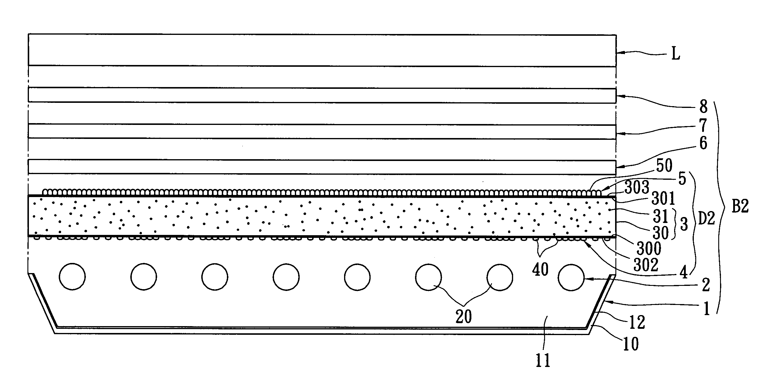
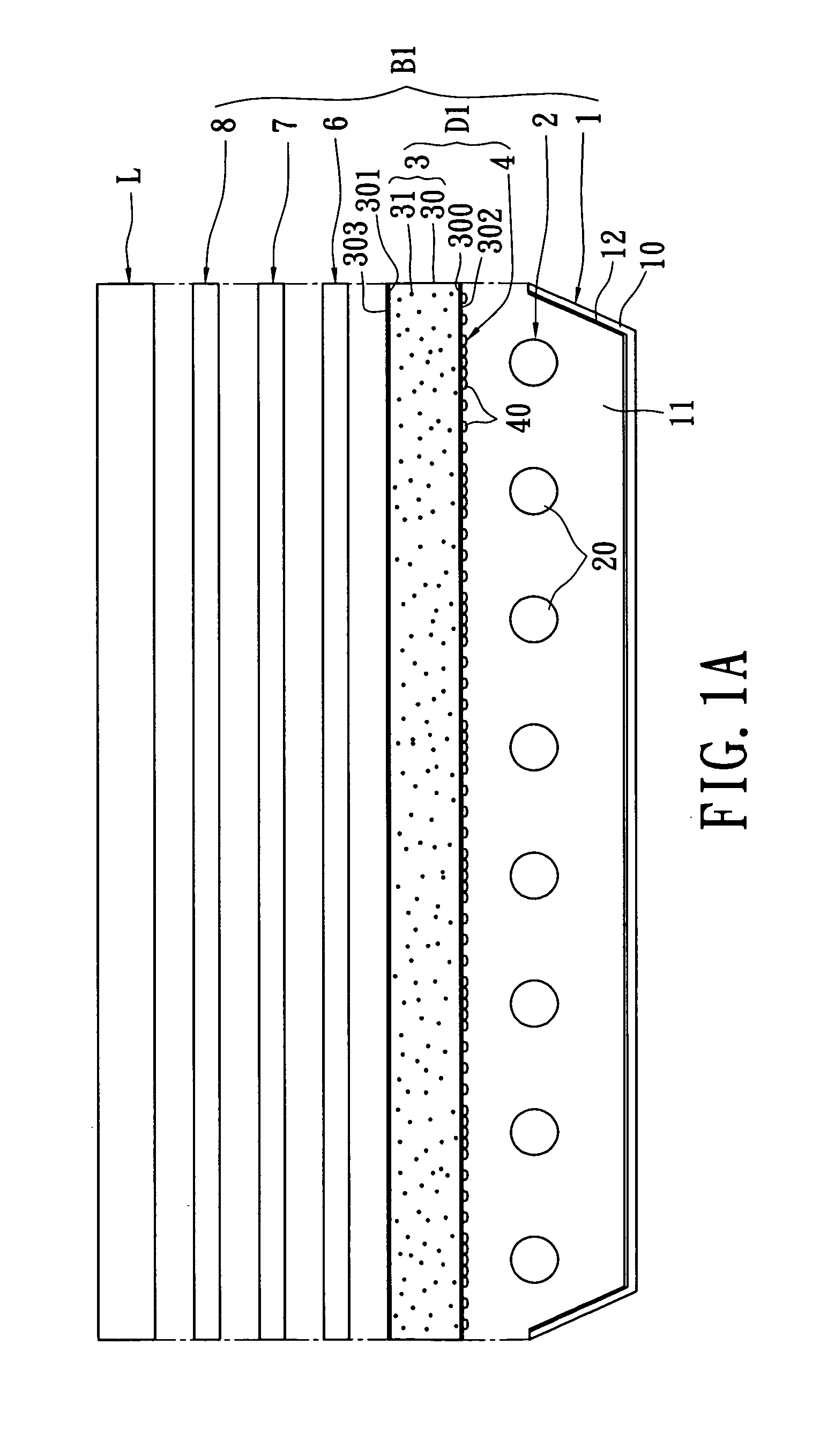
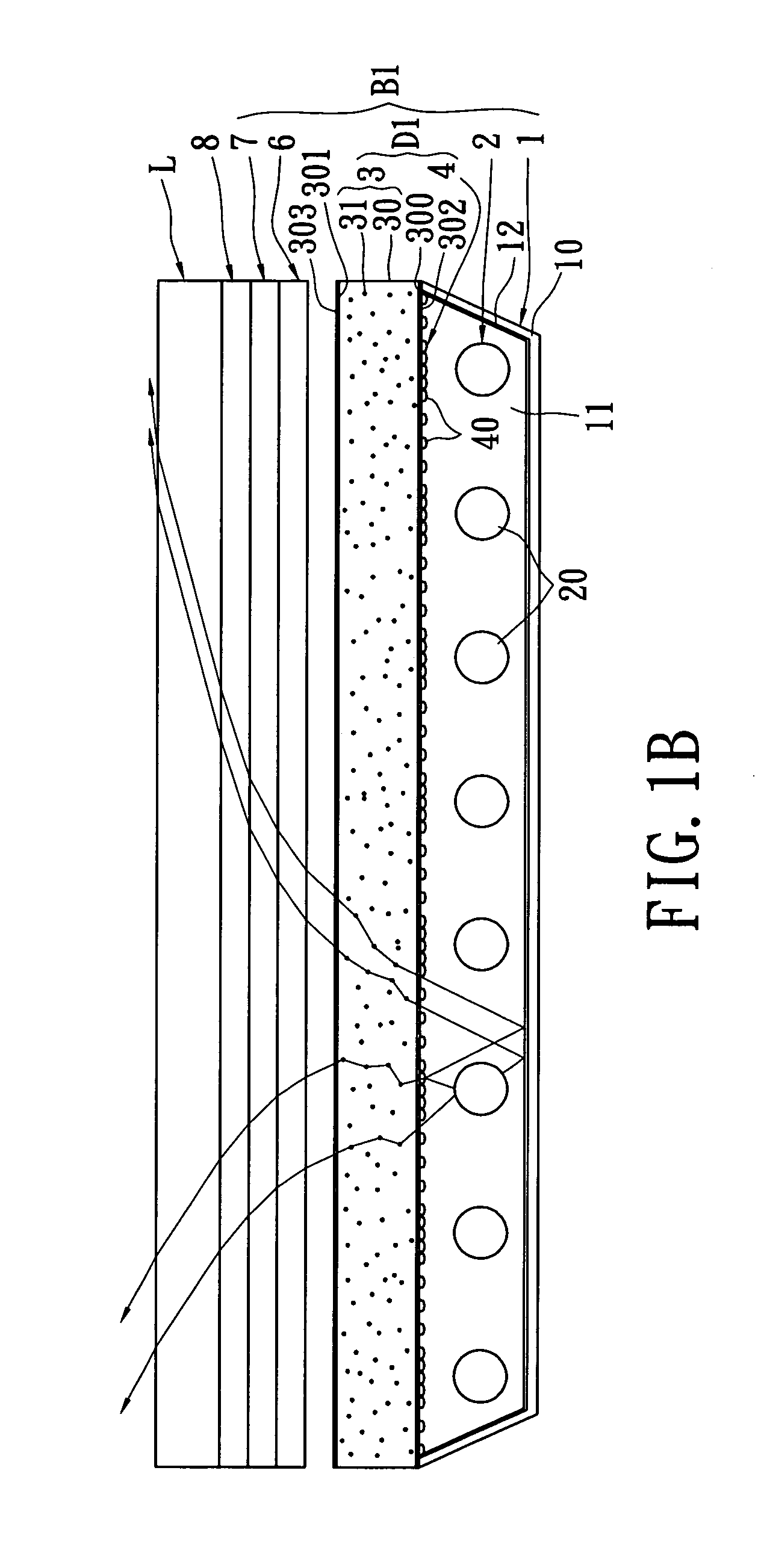
[0027]Refer now to FIGS. 1A and 1B, as shown therein, a first embodiment of the present invention provides a liquid crystal display, comprising: a liquid crystal display panel L and a backlight module B1, and the backlight module B1 is installed under the liquid crystal display panel L, offering required light source for the liquid crystal display panel L. Additionally, the backlight module B1 consists of: a reflection unit 1, a light emitting unit 2, and a compound diffusion plate structure D1; as well as a first diffusion film 6, a second diffusion film 7 and a third diffusion film 8 sequentially installed over the compound diffusion plate structure D1.

[0028]The reflection unit 1 has a reflection plate 10, an installation space 11 formed by the surrounding reflection plate 10, and a reflection coating 12 formed on the internal surface of the reflection plate 10, wherein the reflection coating 12 is usually formed by a film of high reflectivity feature, commonly attached onto the r...


PUM

PropertyMeasurementUnit
particle diameteraaaaaaaaaa
sizeaaaaaaaaaa

Abstract

A liquid crystal display, comprising: a liquid crystal display panel and a backlight module. The backlight module comprising: a reflection unit, a light emitting unit, and a compound diffusion plate structure. The light emitting unit has a plurality of light emitting components installed within the installation space of the reflection unit. The compound diffusion plate structure is placed on one side of the light emitting unit, comprising: a body unit and a printing micro diffusion unit. The body unit has a main layer, and a plurality of micro diffusion particles formed inside the body unit, allowing light to diffuse within the body unit. The printing micro diffusion unit has a plurality of convex lens units formed on a light entrance plane or a light exit plane of the body unit by means of printing.

Description

BACKGROUND OF THE INVENTION[0001]1. Field of the Invention[0002]The present invention is related to a compound diffusion plate structure, backlight module, and liquid crystal display; in particular, to a compound diffusion plate structure capable of increasing brightness and range of angle of view, as well as a backlight module and a liquid crystal display using the compound diffusion plate structure.[0003]2. Description of Related Art[0004]Since the demand on the size of backlight module keeps increasing, conventional small to middle size backlight modules of side-light type have been gradually substituted by direct-light type backlight modules. In a backlight module of side-light type, light enters on one side of light guiding plate, and repeatedly reflects and diffuses inside the light guiding plate based on the total reflection principle in order to enhance the light range and uniformity; afterward, the total reflection is broken by an optically designed micro structure to unifo...

Claims


Application Information

Patent Timeline
Patent Type & Authority Patents(United States)
IPC IPC(8): G02F1/1335
CPCG02F1/133606G02F1/133611
Inventor LIN, CHAO-YINGWU, YING YUANLIN, CHUN-YUCHANG, JEN-HUAICHEN, CHUNG YU
Owner ENTIRE TECH CO LTD
Why Eureka
Try Eureka