Turbine airfoil cooling system with curved diffusion film cooling hole

a cooling system and diffusion film technology, applied in the field of hollow turbine airfoils, can solve the problems of reducing the useful life of the turbine airfoil, damage to the turbine blade, and localized hot spots, so as to facilitate the reduction of over-cooling of the airfoil, reduce the overall potential of the internal film cooling hole, and reduce the heat of the cooling air.

Inactive Publication Date: 2012-01-10
SIEMENS ENERGY INC
View PDF13 Cites 38 Cited by
  • Summary
  • Abstract
  • Description
  • Claims
  • Application Information

AI Technical Summary

Benefits of technology

[0010]During operation, cooling fluids, such as gases, are passed through the cooling system. In particular, cooling fluids may pass into the internal cavity, enter the inlet, pass through the curved diffusion film cooling hole, and exit the diffusion film cooling hole through the outlet. The inlet may operate to meter the flow of cooling fluids through the diffusion film cooling hole. Downstream of the inlet, the remaining portions of the diffusion film cooling hole may enable the cooling fluids to undergo multiple expansion such that more efficient use of the cooling fluids may be used during film cooling applications. Little or no expansion occurs at the first sidewall, which is the upstream side, of the diffusion film cooling hole. This configuration with the different radii for the first and second sidewalls enables an even larger outlet of the diffusion film cooling hole, which translates into better film coverage and yields better film cooling. The curved first and second sidewalls create a smooth diffusion section that allows film cooling flow to spread out of the diffusion film cooling hole at the outlet better than conventional configurations. Additionally, the diffusion film cooling hole minimizes film layer shear mixing with the hot gas flow and thus, yields a higher level of cooling fluid effectiveness.
[0019]Another advantage of the diffusion film cooling hole is that more convective cooling occurs at the external half of the airfoil than at the inner half of the airfoil, thereby achieving a more balanced thermal design for the leading edge.

Problems solved by technology

In addition, turbine airfoils often contain cooling systems for prolonging the life of the turbine airfoils and reducing the likelihood of failure as a result of excessive temperatures.
However, centrifugal forces and air flow at boundary layers often prevent some areas of the turbine airfoil from being adequately cooled, which results in the formation of localized hot spots.
Localized hot spots, depending on their location, can reduce the useful life of a turbine airfoil and can damage a turbine blade to an extent necessitating replacement of the airfoil.
Nonetheless, many conventional diffusion orifices are configured such that cooling fluids are exhausted and mix with the hot gas path and become ineffective.

Method used


Image

  • Turbine airfoil cooling system with curved diffusion film cooling hole
  • Turbine airfoil cooling system with curved diffusion film cooling hole
  • Turbine airfoil cooling system with curved diffusion film cooling hole

Examples


Embodiment Construction

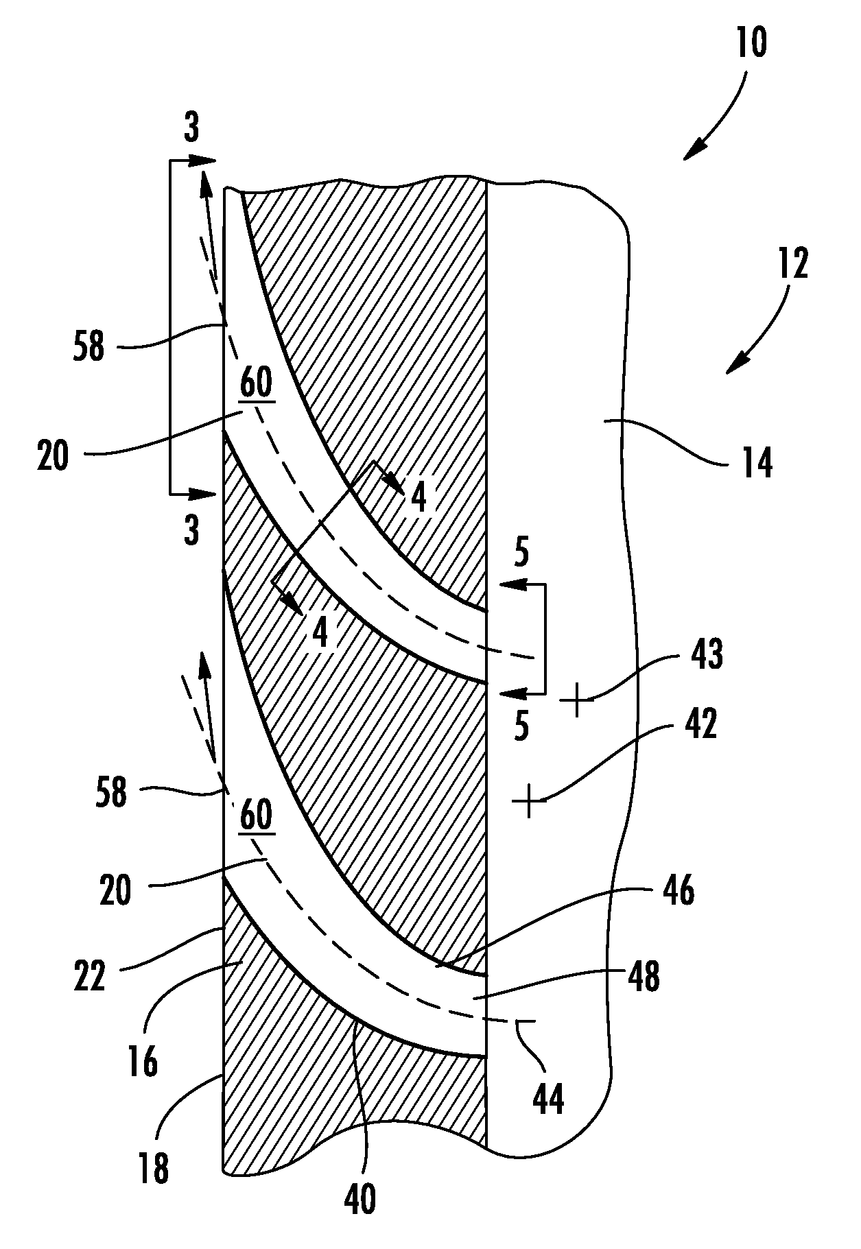
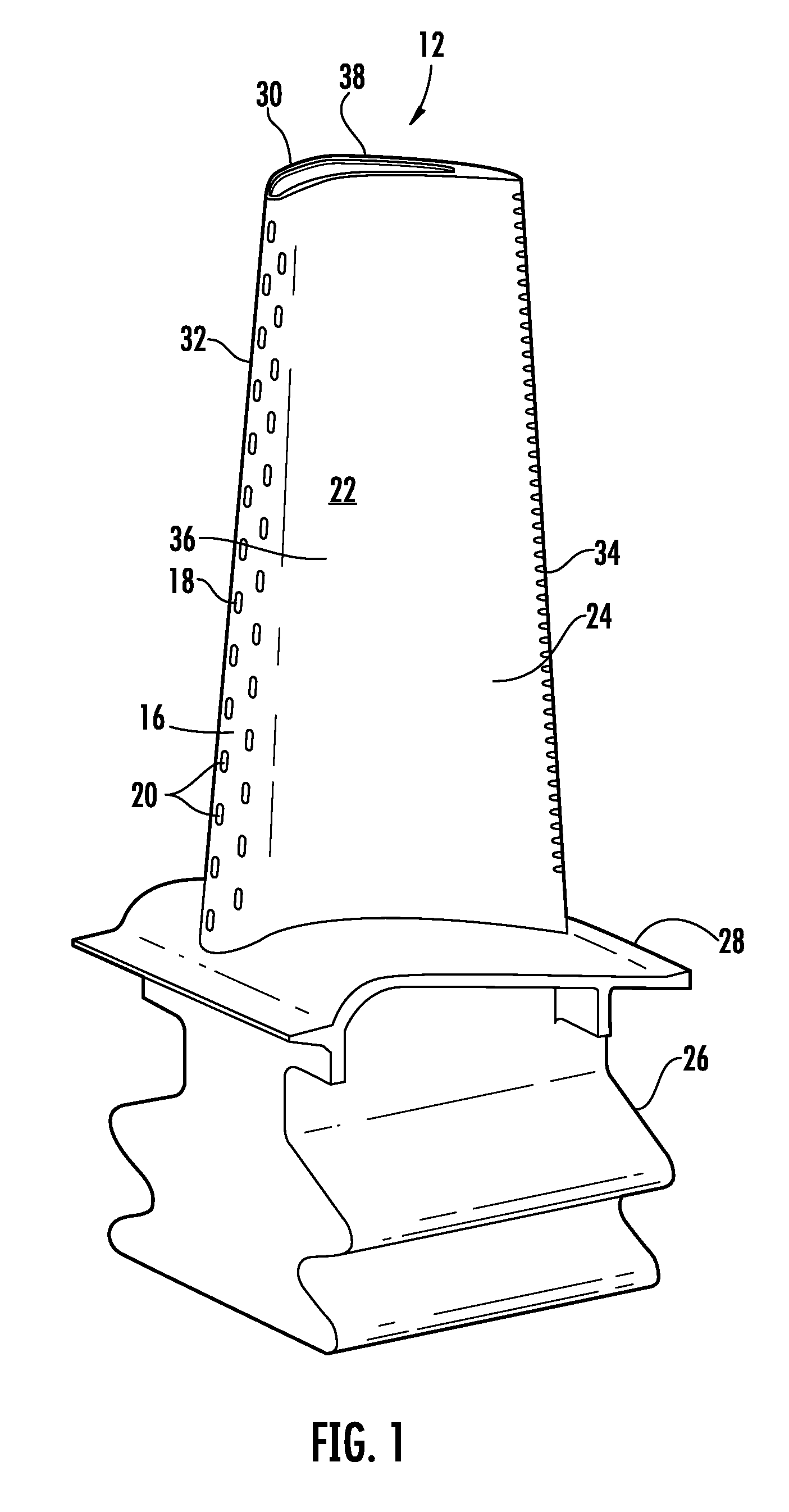
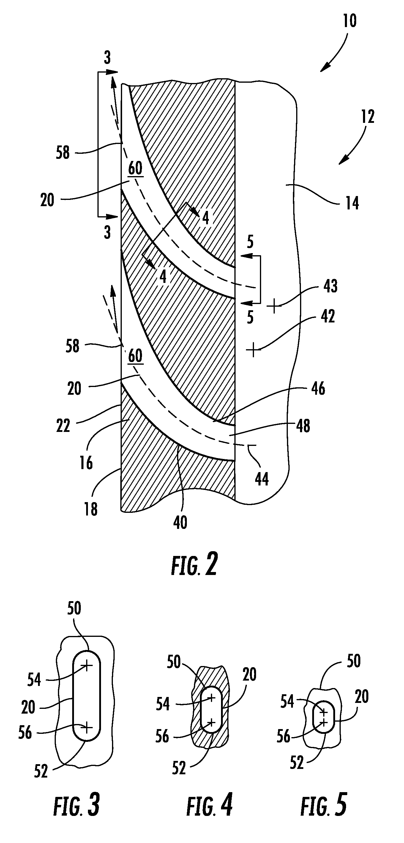
[0027]As shown in FIGS. 1-5, this invention is directed to a turbine airfoil cooling system 10 for a turbine airfoil 12 used in turbine engines. In particular, the turbine airfoil cooling system 10 is directed to a cooling system 10 having an internal cavity 14, as shown in FIG. 2, positioned between outer walls 16 forming a housing 18 of the turbine airfoil 12. The cooling system 10 may include a diffusion film cooling hole 20 in the outer wall 16 that may be adapted to receive cooling fluids from the internal cavity 14, meter the flow of cooling fluids through the diffusion film cooling hole 20, and release the cooling fluids into a film cooling layer proximate to an outer surface 22 of the airfoil 12. The diffusion film cooling hole 20 may be curved and include an ever increasing cross-sectional area across that allow cooling fluids to diffuse to create better film coverage and yield better cooling of the turbine airfoil.

[0028]The turbine airfoil 12 may be formed from a generally...


PUM


Abstract

A cooling system for a turbine airfoil of a turbine engine having at least one diffusion film cooling hole positioned in an outer wall defining the turbine airfoil is disclosed. The diffusion film cooling hole includes a first sidewall having a first radius of curvature about an axis generally orthogonal to a centerline of cooling fluid flow through the diffusion film cooling hole and a second sidewall having a second radius of curvature about an axis generally orthogonal to the centerline of cooling fluid flow through the at least one diffusion film cooling hole. The radii of curvature of the first and second sidewalls are different such that the diffusion film cooling hole includes an ever increasing cross-sectional area moving from an inlet to an outlet, thereby diffusing and reducing the velocity of cooling fluids flowing there through.

Description

CROSS-REFERENCE TO RELATED APPLICATION[0001]This patent application claims the benefit of U.S. Provisional Patent Application No. 61 / 097,326, filed Sep. 16, 2008, which is incorporated by reference in its entirety.FIELD OF THE INVENTION[0002]This invention is directed generally to turbine airfoils, and more particularly to cooling systems in hollow turbine airfoils.BACKGROUND[0003]Typically, gas turbine engines include a compressor for compressing air, a combustor for mixing the compressed air with fuel and igniting the mixture, and a turbine blade assembly for producing power. Combustors often operate at high temperatures that may exceed 2,500 degrees Fahrenheit. Typical turbine combustor configurations expose turbine blade assemblies and turbine vanes to these high temperatures. As a result, turbine airfoils must be made of materials capable of withstanding such high temperatures. In addition, turbine airfoils often contain cooling systems for prolonging the life of the turbine ai...

Claims


Application Information

Patent Timeline
Patent Type & Authority Patents(United States)
IPC IPC(8): B63H1/14F04D29/58F01D5/14F03D11/02B63H7/02B63H1/28B64C11/00F01D5/20F01D5/18F01D5/08B64C11/16
CPCF01D5/186F05D2240/121F05D2240/303F05D2260/202
Inventor LIANG, GEORGE
Owner SIEMENS ENERGY INC
Why Eureka
Try Eureka