Method for manufacturing liquid crystal display device

a liquid crystal display and liquid crystal technology, applied in the field of liquid crystal display devices, can solve the problems of long time and difficult injection of liquid crystal using the dipping method, and achieve the effects of improving yield and productivity, high response speed, and high accuracy

Inactive Publication Date: 2012-01-31
SEMICON ENERGY LAB CO LTD
View PDF27 Cites 13 Cited by
  • Summary
  • Abstract
  • Description
  • Claims
  • Application Information

AI Technical Summary

Benefits of technology

[0009]It is an object of the present invention to prevent alignment disorder of liquid crystal molecules, which is caused in manufacturing steps, and to manufacture a liquid crystal display device including a uniform liquid crystal layer in which liquid crystal molecules are aligned with high accuracy. Therefore, the present invention provides a technique for manufacturing a liquid crystal display device which is capable of fast response and high performance, and has high image quality with reduced display defects, with high yield.
[0011]After dropping droplets of smectic liquid crystal, a pair of substrates are attached and the smectic liquid crystal quickly spreads on the alignment film in a direction perpendicular to the rubbing direction. This is because smectic liquid crystal is liquid crystal which has a layer structure and has a layer direction (a direction in which layers are formed with alignment of liquid crystal molecules) which is perpendicular to the rubbing direction. Accordingly, by dropping liquid crystal so that droplets are aligned in a direction parallel to the rubbing direction of the alignment film, a bubble do not get into the liquid crystal and collision traces of the droplets do not remain when the liquid crystal spreads to fill a seal pattern of a sealant which has an opening. Therefore, alignment disorder of liquid crystal molecules due to a bubble or collision of the droplets can be prevented.
[0012]In the present invention, a seal pattern of a sealant is provided with an opening. An excess liquid crystal material which is dropped into the frame of the sealant is drained away from the seal pattern through the opening of the seal pattern. Therefore, if the amount of liquid crystal which is dropped is larger than needed, the amount of liquid crystal which is sealed can be controlled in an attaching step. Accordingly, it is not necessary to precisely control the amount of liquid crystal dropped in a dropping step of liquid crystal, which leads to improvement in yield and productivity. The seal pattern may have one opening or a plurality of openings.
[0013]Therefore, a uniform liquid crystal layer of smectic liquid crystal in which alignment disorder of liquid crystal molecules, which is caused in manufacturing steps, can be prevented and liquid crystal molecules are aligned with high accuracy can be formed. Since smectic liquid crystal like ferroelectric liquid crystal has a high response speed, a liquid crystal display device with a high response speed and reduced display defects can be manufactured by using a liquid crystal layer formed according to the present invention. Therefore, a liquid crystal display device with improved performance and image quality can be manufactured with high yield according to the present invention.
[0020]In the present invention, a seal pattern of a sealant is provided with an opening, so that an excess liquid crystal material which is dropped into the seal pattern of the sealant is drained away from the seal pattern of the sealant through the opening of the seal pattern of the sealant. Therefore, if the amount of liquid crystal which is dropped is larger than needed, the amount of liquid crystal which is sealed can be controlled in an attaching step. Accordingly, it is not necessary to precisely control the amount of liquid crystal dropped in a dropping step of liquid crystal, which leads to improvement in yield and productivity.
[0021]According to the present invention, a uniform liquid crystal layer of smectic liquid crystal in which alignment disorder of liquid crystal molecules which is caused in manufacturing steps, can be prevented and liquid crystal molecules are aligned with high accuracy can be formed. Since smectic liquid crystal like ferroelectric liquid crystal has a high response speed, a liquid crystal display device with a high response speed and reduced display defects can be manufactured by using a liquid crystal layer formed according to the present invention. Therefore, a liquid crystal display device with improved performance and image quality can be manufactured with high yield according to the present invention.

Problems solved by technology

However, there have been problems in that injection of liquid crystal using a dipping method is difficult and needs long time, and alignment disorder is occurred by injection because the smectic liquid crystal has high viscosity at room temperature.

Method used


Image

  • Method for manufacturing liquid crystal display device
  • Method for manufacturing liquid crystal display device
  • Method for manufacturing liquid crystal display device

Examples


embodiment mode 1

[0042]This embodiment mode describes an example of a liquid crystal display device including a uniform liquid crystal layer in which alignment disorder of liquid crystal molecules is prevented and liquid crystal molecules are aligned with high accuracy in order to achieve improved performance and image quality.

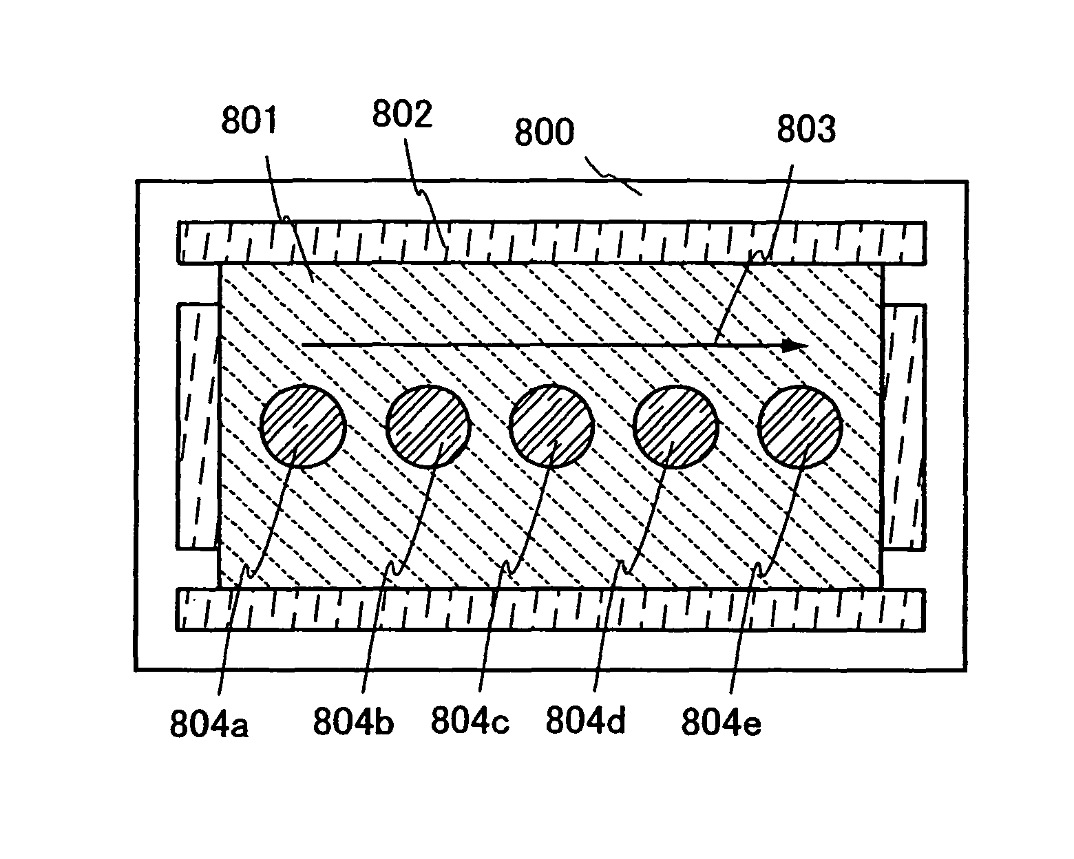
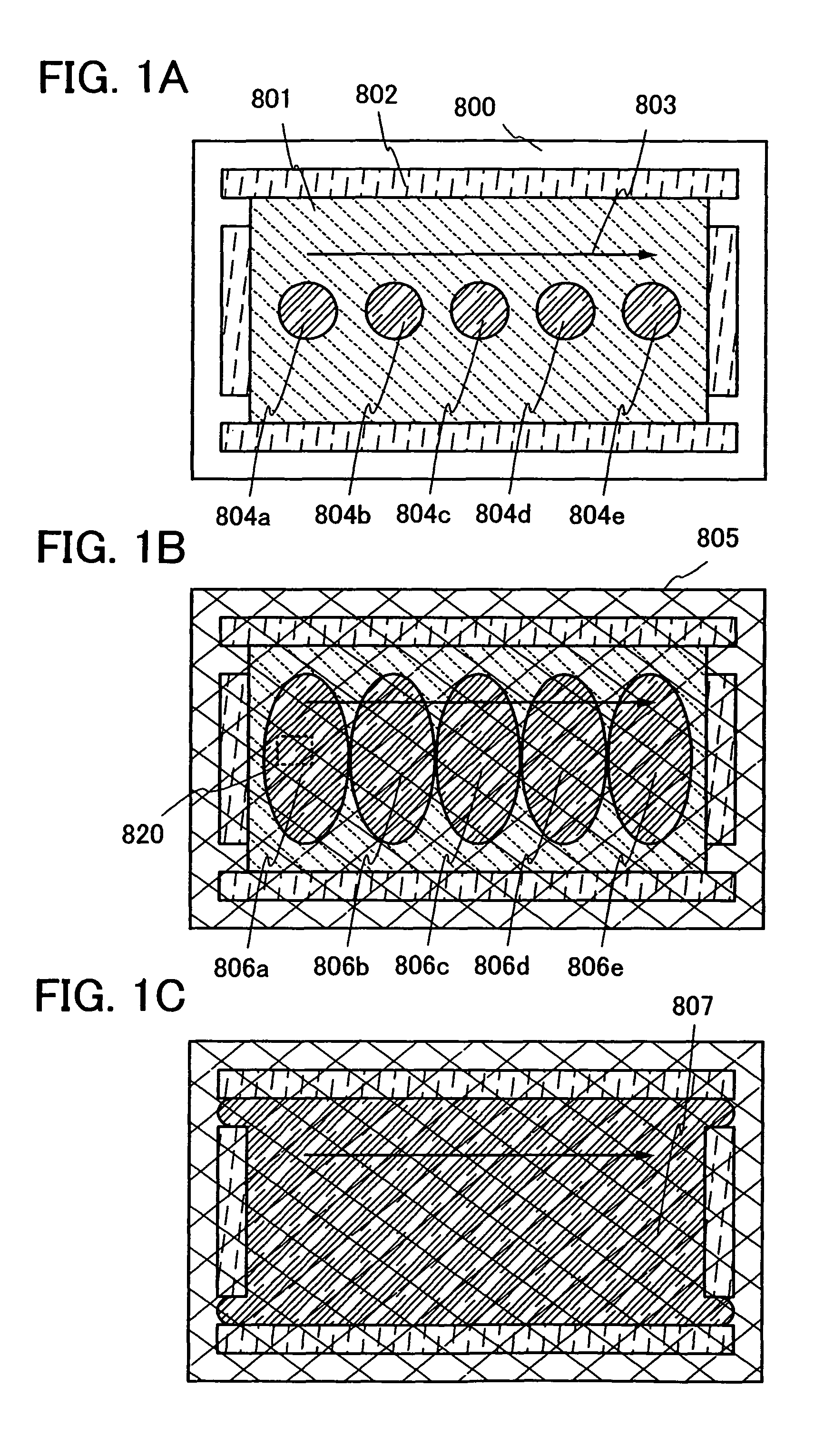
[0043]FIGS. 1A to 1C show a method for manufacturing a liquid crystal display device of this embodiment mode according to the present invention. In FIGS. 1A to 1C, an insulating layer 801 serving as an alignment film and a sealant 802 having an opening are provided over a first substrate 800. The insulating layer 801 has its surface rubbing-treated in a rubbing direction which is denoted by an arrow 803 to serve as an alignment film. The sealant 802 has four openings at both ends of short sides. The short sides of the sealant 802 are orthogonal to the rubbing direction. (the arrow 803).

[0044]As shown in FIG. 1A, smectic liquid crystal is dropped as droplets 804a, 804b, 804c, 8...

embodiment mode 2

[0078]This embodiment mode describes an example of a liquid crystal display device including a uniform liquid crystal layer in which alignment disorder of liquid crystal molecules is prevented and liquid crystal molecules are aligned with high accuracy in order to achieve improved performance and image quality. In specific, a passive matrix liquid crystal display device is described.

[0079]A passive matrix liquid crystal display device of this embodiment mode to which the present invention is applied is described. FIG. 5A shows a top view of the liquid crystal display device and FIG. 5B shows a cross-sectional view taken along line A-B in FIG. 5A. Note that in FIG. 5A, an insulating layer 1704 serving as an alignment film, a coloring layer, a substrate 1710 serving as a counter substrate, a polarizing plate 1714, and the like are provided as shown in FIG. 5B, although they are omitted and not shown in FIG. 5A.

[0080]In FIGS. 5A and 5B, a substrate 1700 provided with pixel electrode la...

embodiment mode 3

[0098]This embodiment mode describes an example of a liquid crystal display device including a uniform liquid crystal layer in which alignment disorder of liquid crystal molecules is prevented and liquid crystal molecules are aligned with high accuracy in order to achieve improved performance and image quality. In this embodiment mode, a liquid crystal display device having a structure different from that in Embodiment Mode 2 is described. In specific, an active matrix liquid crystal display device is described.

[0099]FIG. 6A shows a top view of a liquid crystal display device and FIG. 6B shows a cross-sectional view taken along line E-F in FIG. 6A. Note that in FIG. 6A, a liquid crystal layer, and an alignment film, a counter electrode layer, a coloring layer, and the like, which are provided on the counter substrate side are provided as shown in FIG. 6B, although they are omitted and not shown in FIG. 6A.

[0100]First wirings which extend in a first direction and second wirings which...


PUM

PropertyMeasurementUnit
temperatureaaaaaaaaaa

Abstract

Smectic liquid crystal is dropped by a dropping method in which a plurality of droplets of smectic liquid crystal are dropped to an alignment film so that the droplets are aligned in a line which is parallel to a rubbing direction of the alignment film which is formed in a region surrounded by a seal pattern of a sealant having an opening over a substrate. Excess liquid crystal is drained away from the seal pattern of a sealant through the opening of the seal pattern.

Description

BACKGROUND OF THE INVENTION[0001]1. Field of the Invention[0002]The present invention relates to liquid crystal display devices.[0003]2. Description of the Related Art[0004]In recent years, liquid crystal display devices are used in a wide range of fields such as liquid crystal televisions, PDAs, mobile phones, and office automation equipment like personal computers, as well as clocks and calculators.[0005]In a liquid crystal display device, liquid crystal is sealed between two light transmitting substrates. When voltage is applied, an orientation of liquid crystal molecules is changed to change light transmittance, so that a predetermined image or the like is displayed optically.[0006]Since liquid crystal display devices can be driven with low power and can be reduced in thickness and weight, further improvement has been made. Ferroelectric liquid crystal which is smectic liquid crystal has attracted attention as a liquid crystal material which allows improvement in a viewing angle...

Claims


Application Information

Patent Timeline
Patent Type & Authority Patents(United States)
IPC IPC(8): G02F1/1341
CPCB32B37/24G02F1/1341B32B2037/243B32B2309/02B32B2309/04B32B2310/0831B32B2310/0843B32B2311/00B32B2377/00B32B2379/08B32B2457/202G02F1/1339G02F1/13454G02F1/136277G02F1/1368G02F1/141G02F2001/13415G02F1/13415
Inventor ISHITANI, TETSUJINISHI, TAKESHI
Owner SEMICON ENERGY LAB CO LTD
Why Eureka
Try Eureka