
Vertical non-bladdered fuel tank for a ducted fan vehicle
a technology of ducted fan and fuel tank, which is applied in the direction of mechanical equipment, transportation and packaging, transportation items, etc., can solve the problems of unduly shortening the run time of the engine, affecting the refueling process, and affecting the refueling time. , to achieve the effect of simplifying the refueling process and reducing the refueling tim
- Summary
- Abstract
- Description
- Claims
- Application Information
AI Technical Summary
Benefits of technology
Problems solved by technology
Method used
Image

Examples
Embodiment Construction
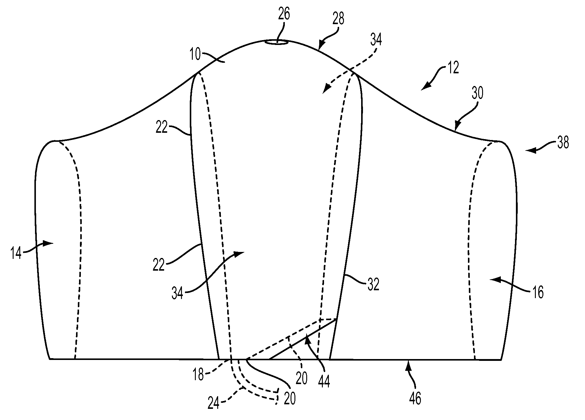
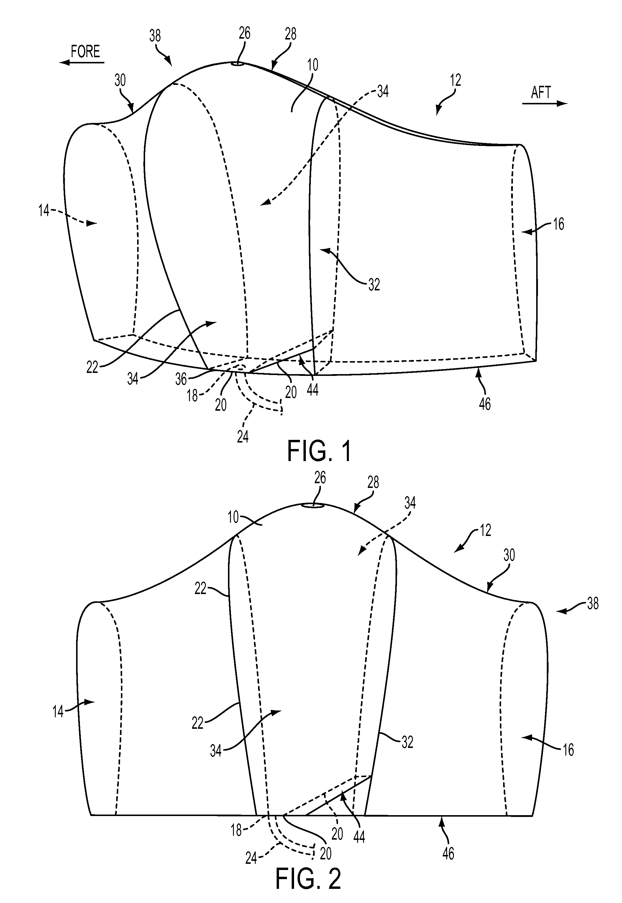
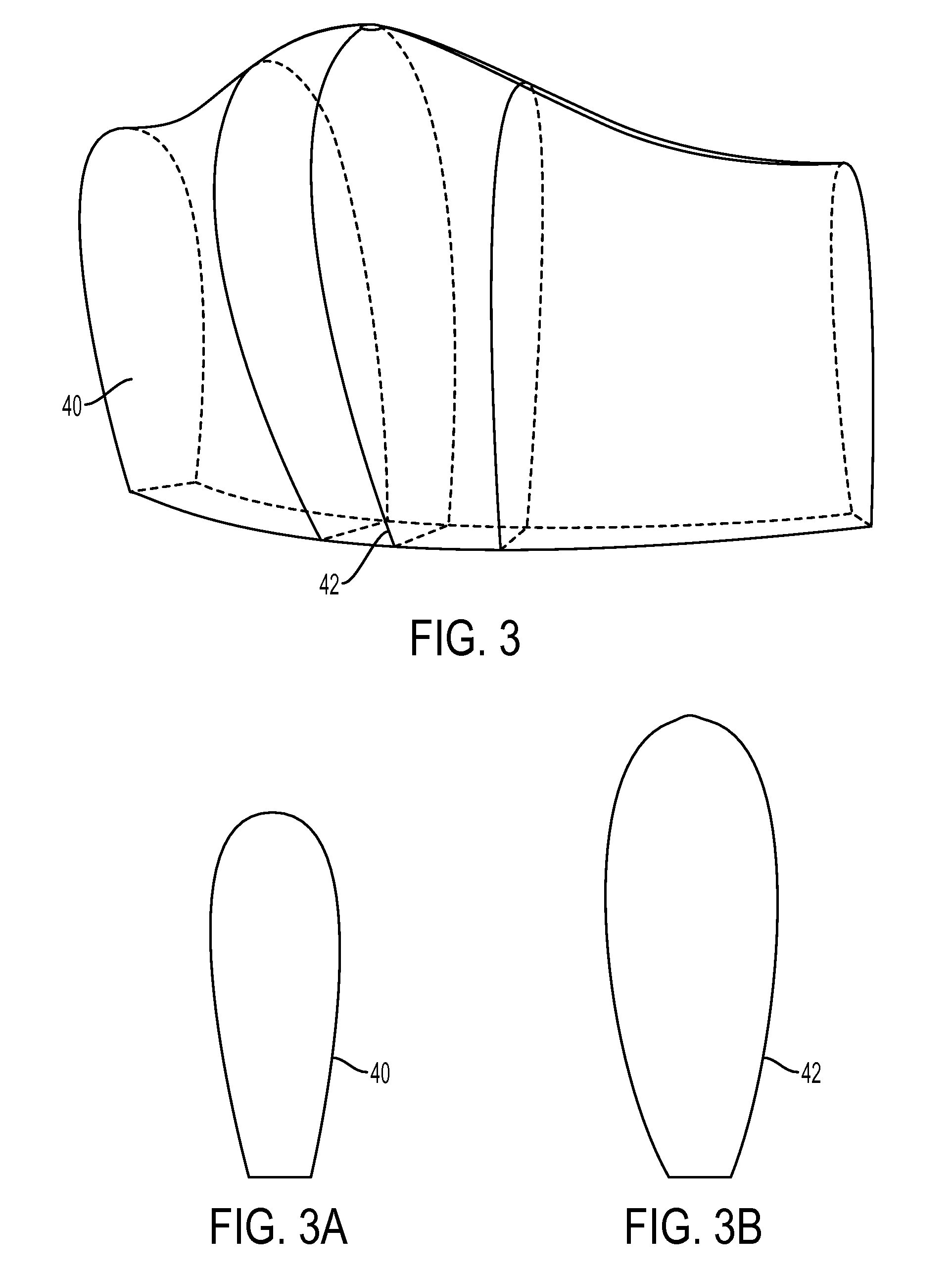
[0018]In a first aspect, the present invention provides a vertical non-bladdered fuel tank 10 for a ducted fan vehicle comprising: (a) a pod 12 that releasably connects to a core vehicle of a ducted fan vehicle, (b) a vertical fuel tank 10 contained by the pod 12, wherein the vertical fuel tank 10 is centered between the fore and aft sides 14, 16 of the pod 12, (c) an outlet 18 in a floor 20 of the vertical fuel tank 10 located adjacent to a sidewall 22 on the fore side of the vertical fuel tank 10, wherein the outlet 18 is coupled to a draw tube 24 contained by the core vehicle, and (d) a pressure release vent 26 located at the highlight 28 of the pod's duct 30.
[0019]As used herein, a pod 12 is a streamlined, detachable housing that may contain various payloads, such as weapons or fuel. The pods 12 connect to a core vehicle to form a complete duct on a UAV. The arrangement of the various pods 12 relative to one another is limited only by the location of the connectors on the core v...
PUM
 Abstract
Description
Claims
Application Information