Vertical non-bladdered fuel tank for a ducted fan vehicle

Inactive Publication Date: 2010-05-13
HONEYWELL INT INC
View PDF37 Cites 1 Cited by
  • Summary
  • Abstract
  • Description
  • Claims
  • Application Information

AI Technical Summary

Benefits of technology

[0009]The discovery presented herein outlines a vertical non-bladdered fuel tank and a method and system for implementing the same on a UAV, which has a beneficial effect on the

Problems solved by technology

When the engine ingests air or fuel vapor, it typically stalls.
With conventional piccolo tubes, the engine often stalls due to air and/or fuel vapor ingestion prior to consumption of all of the fuel contained in the fuel bladder.
As a result, the run time of the engine is unduly shortened.
Additionally, closed (i.e., unvented) fuel systems conventionally rely on the integrity of the vacuum created and maintained within sealed containers or collapsible bladders to prevent the intrusion of air and/or vapor into the system.
Such systems generally do not provide countermeasures to remove internally generated fuel vapor and/or air that enters due to improper fueling or leaks.
As a result, the proportion of fuel within the bladder that is consumed prior to engine seizure or fuel starvation

Method used


Image

  • Vertical non-bladdered fuel tank for a ducted fan vehicle
  • Vertical non-bladdered fuel tank for a ducted fan vehicle
  • Vertical non-bladdered fuel tank for a ducted fan vehicle

Examples


Embodiment Construction

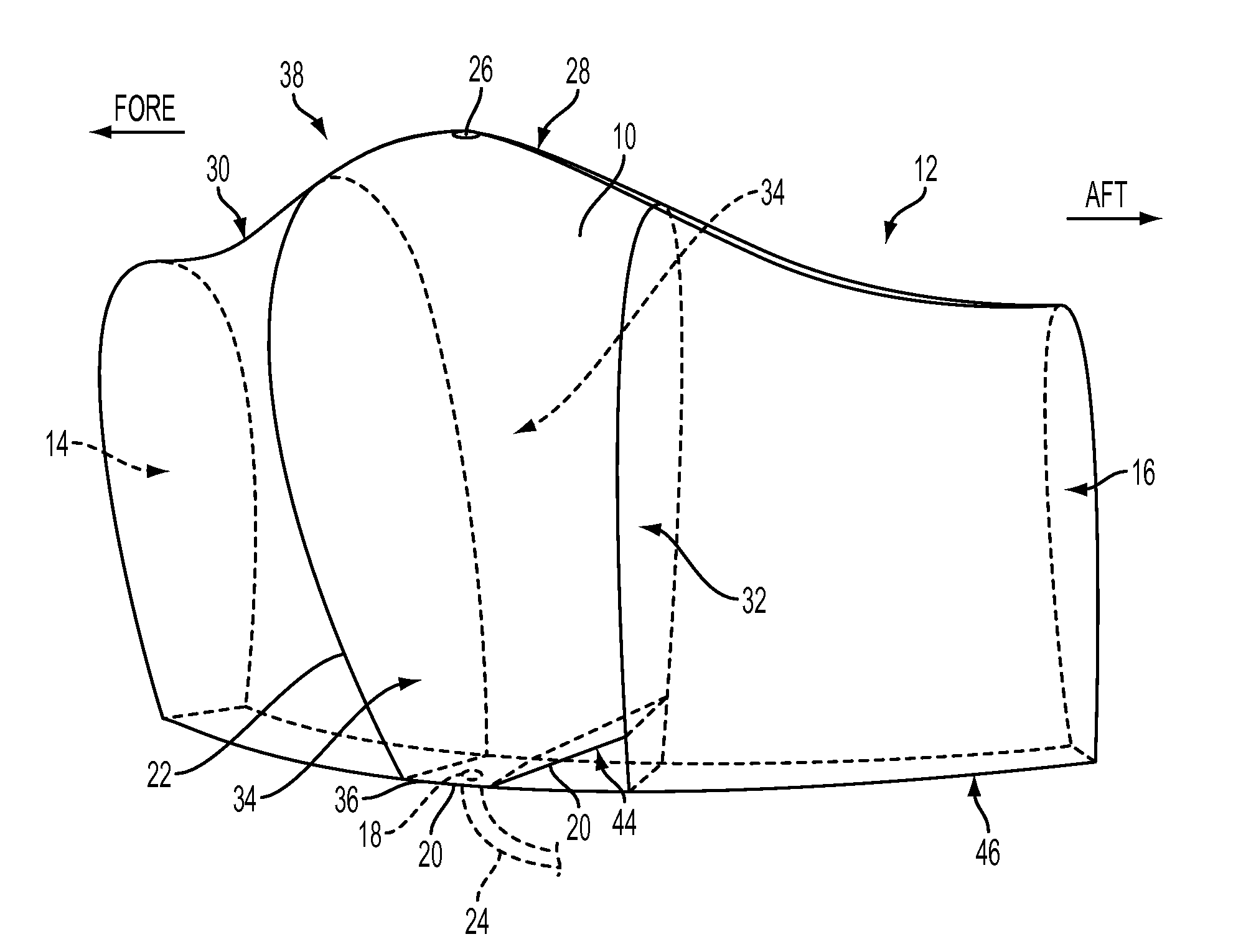
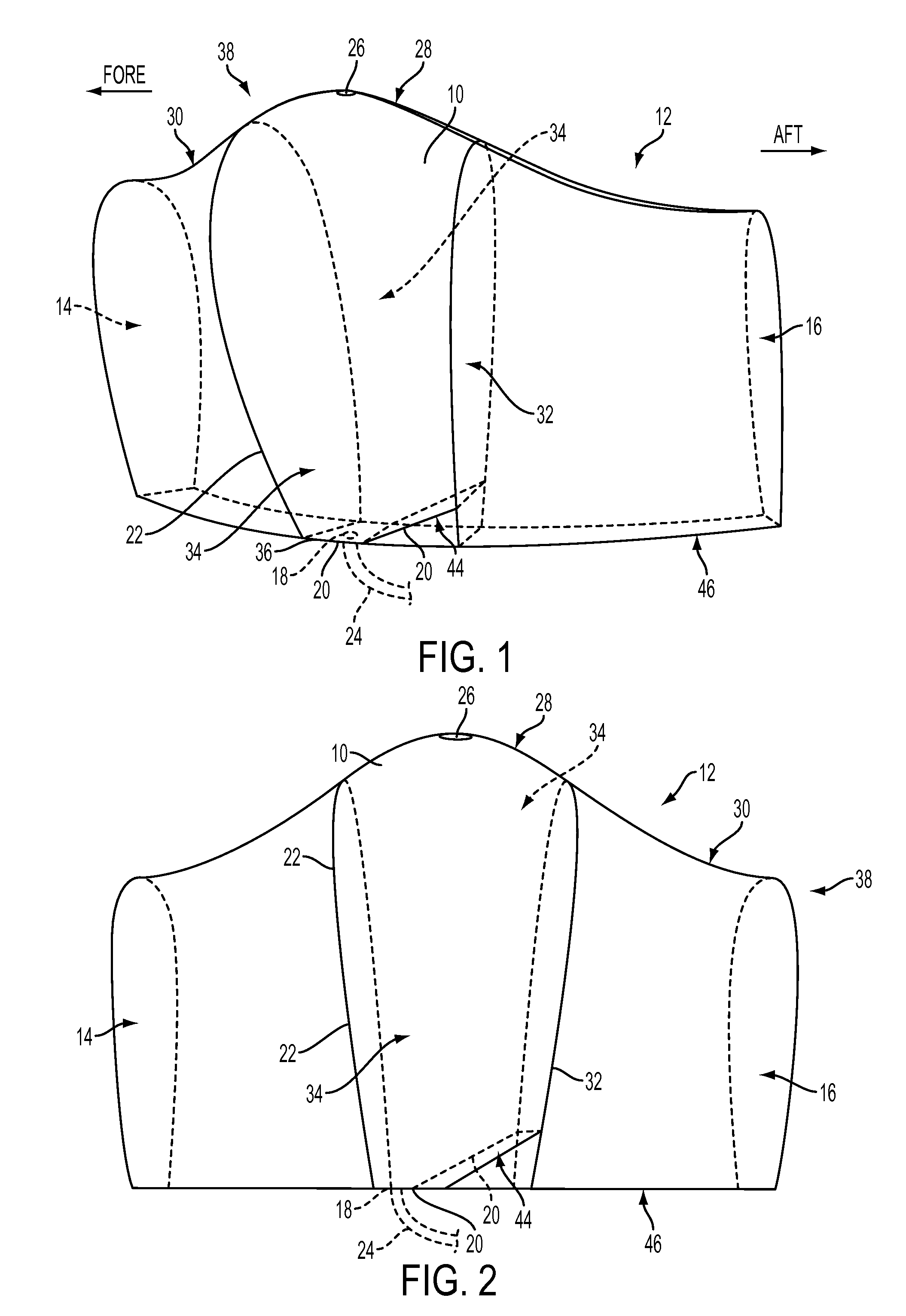
[0018]In a first aspect, the present invention provides a vertical non-bladdered fuel tank 10 for a ducted fan vehicle comprising: (a) a pod 12 that releasably connects to a core vehicle of a ducted fan vehicle, (b) a vertical fuel tank 10 contained by the pod 12, wherein the vertical fuel tank 10 is centered between the fore and aft sides 14, 16 of the pod 12, (c) an outlet 18 in a floor 20 of the vertical fuel tank 10 located adjacent to a sidewall 22 on the fore side of the vertical fuel tank 10, wherein the outlet 18 is coupled to a draw tube 24 contained by the core vehicle, and (d) a pressure release vent 26 located at the highlight 28 of the pod's duct 30.

[0019]As used herein, a pod 12 is a streamlined, detachable housing that may contain various payloads, such as weapons or fuel. The pods 12 connect to a core vehicle to form a complete duct on a UAV. The arrangement of the various pods 12 relative to one another is limited only by the location of the connectors on the core v...


PUM


Abstract

A vertical non-bladdered fuel tank for a ducted fan vehicle comprising: a pod that releasably connects to a core vehicle of a ducted fan vehicle, a vertical fuel tank contained by the pod, wherein the vertical fuel tank is centered between the fore and aft sides of the pod, an outlet in a floor of the vertical fuel tank located adjacent to a sidewall on the fore side of the vertical fuel tank, wherein the outlet is coupled to a draw tube contained by the core vehicle, and a pressure release vent located at the highlight of the pod's duct.

Description

GOVERNMENT RIGHTS[0001]The United States government may have certain rights in this invention pursuant to Government Contract # W56HZV-05-C-0724 with the U.S. Army (TACOM).BACKGROUND OF THE INVENTION[0002]In conventional micro-air vehicles and other ducted fan unmanned aerial vehicles, the vertical duct is unified and indivisible. Within this indivisible duct, the fuel is typically contained in a shallow, horizontal bladder that lies around the duct. The bladder contains a piccolo tube that similarly circles the entire duct. The piccolo tube comprises an elongated section of tubing that includes one or more openings for taking up fuel from the fuel bladder. The piccolo tube is in turn connected to downstream hoses to facilitate fuel delivery to the engine.[0003]As the engine consumes the fuel contained in the fuel bladder, the air / fuel ratio inside the bladder increases. As the air / fuel ratio reaches high levels (e.g., greater than 1:1), the chances of air or fuel vapor ingestion in...

Claims


Application Information

Patent Timeline
IPC IPC(8): B65D88/12
CPCB64C27/20B64C39/024B64C2201/027B64C2201/108B64C2201/162B64D37/04B64D37/06B64D37/22Y10T137/86212Y10T137/86348B64U10/13B64U30/20B64U50/14
Inventor COLLETTE, DANIEL ROSS
Owner HONEYWELL INT INC
Why Eureka
Try Eureka