Capless fuel-filling closure assembly

Inactive Publication Date: 2011-06-09
FORD GLOBAL TECH LLC
View PDF9 Cites 29 Cited by
  • Summary
  • Abstract
  • Description
  • Claims
  • Application Information

AI Technical Summary

Benefits of technology

[0001]A capless fuel filling system provides a closure for a fuel tank that simplifies refueling by eliminating a removable fuel cap. Specifically, the refueling process is simplified by eliminating the steps of removing the fuel cap prior to fil

Problems solved by technology

However, the inventors herein have recognized some potential issues with such a system.
For example, since the flapper door pivots open in the direction of insertion of the fuel nozzle, the flapper door can be opened inadvertently by conditions other than insertion of a fuel nozzle, such as introduction of a foreign object, debr

Method used


Image

  • Capless fuel-filling closure assembly
  • Capless fuel-filling closure assembly
  • Capless fuel-filling closure assembly

Examples


Embodiment Construction

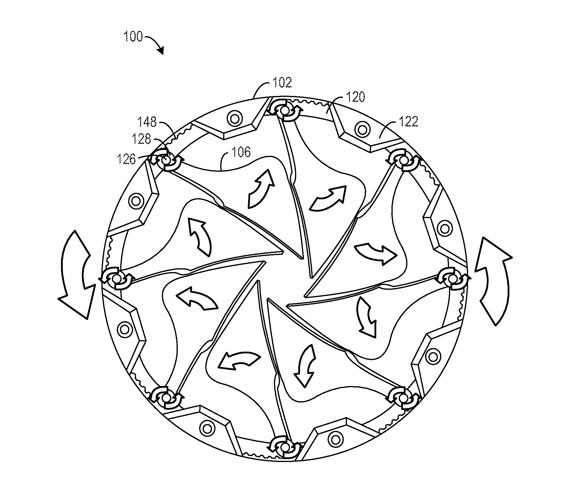
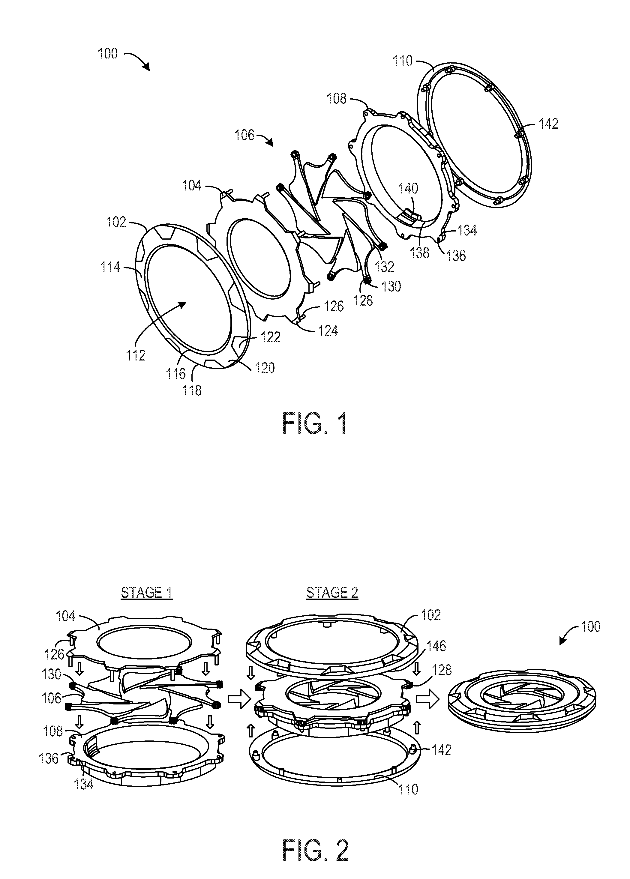
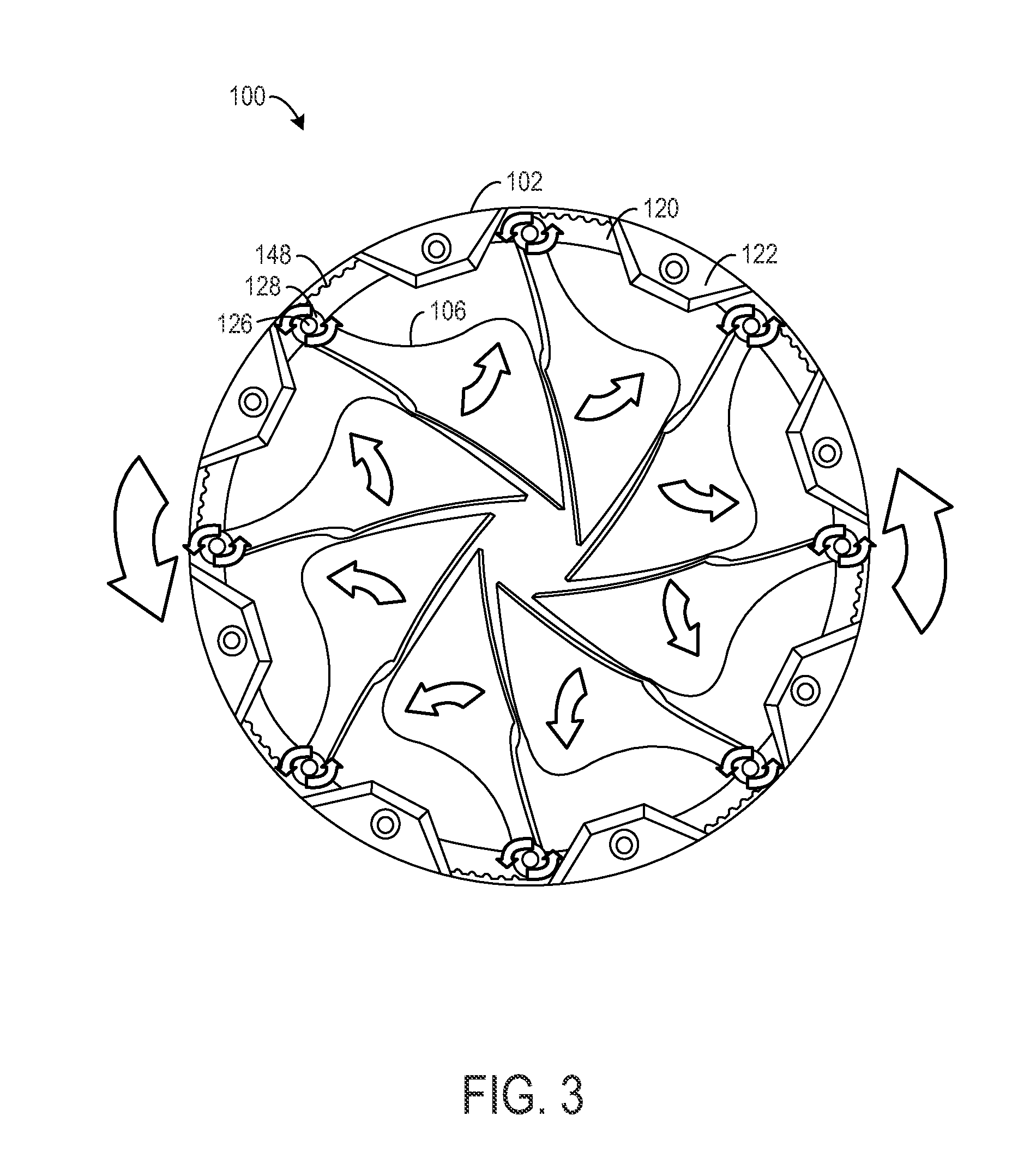
[0014]The following description relates to a closure assembly for a capless fuel filling system of a vehicle that provides a fuel tank seal so as to inhibit environmental contamination while providing easy access for refueling. The closure assembly includes an iris arrangement that is actuatable between a closed position in which the fuel filling system is sealed and an open position to permit access to a fuel nozzle for refueling the fuel tank. The closure assembly of the present disclosure can be implemented as a component of a fuel system to provide a robust seal against environmental contamination and easy access for refueling. On the other hand, the closure assembly of the present disclosure can be retrofitted onto an existing capless fuel filling system to provide additional sealing capabilities. In particular, the closure assembly may be positioned upstream from a flapper door to protect the flapper door from environmental contamination. In either implementation, unlike previ...


PUM


Abstract

A capless fuel filling system for a vehicle including a closure assembly that forms an iris arrangement that is rotatable to form a seal for a fuel filling tube or provide access to the fuel filling tube.

Description

BACKGROUND AND SUMMARY[0001]A capless fuel filling system provides a closure for a fuel tank that simplifies refueling by eliminating a removable fuel cap. Specifically, the refueling process is simplified by eliminating the steps of removing the fuel cap prior to filling the fuel tank and then replacing the fuel cap after filling the fuel tank. Moreover, by eliminating the removable fuel cap, the inconvenience of keeping track of the fuel cap when it is removed from the fuel filling system can be eliminated.[0002]One example of such a capless fuel filling system is illustrated by Foltz in US 2003 / 0098304 A1. Herein, a fuel filler neck, that provides access to a fuel tank, is sealed by a flapper door. The flapper door is pivotally mounted to an interior region of the fuel filler neck adjacent a nozzle-receiving aperture. A torsion spring biases the flapper door against a seating surface of the nozzle-receiving aperture to seal the fuel filler neck. The flapper door pivots open in a ...

Claims


Application Information

Patent Timeline
IPC IPC(8): B60K15/04
CPCB60K2015/0451B60K15/0406
Inventor OGNJANOVSKI, ROBERT G.BALLHEIM, DAVID
Owner FORD GLOBAL TECH LLC
Why Eureka
Try Eureka