Assembly including a device for removably affixing a base to a plate

a technology of a plate and a base, applied in the field of assembly, can solve the problems of affecting the cooperation of the tool, requiring time and space, and affecting the use of the tool, so as to facilitate the affixing and disassembly, facilitate the affixing and assembly, and facilitate the affixing

Inactive Publication Date: 2012-06-19
SALOMON SA
View PDF14 Cites 6 Cited by
  • Summary
  • Abstract
  • Description
  • Claims
  • Application Information

AI Technical Summary

Benefits of technology

[0010]In view of the above, the invention avoids the use of a tool to assemble or disassemble the plate with respect to the base. In addition, the invention makes it easier to immobilize the plate with respect to the base. In particular, the invention provides an easier and quicker way to affix the plate and the base to one another.
[0011]Still further, the invention avoids the disadvantage of losing screws.
[0014]The immobilization mechanism prevents any movement of the plate with respect to the base. Because the mechanism is positioned or actuated by hand, there is no need to use a tool, i.e., the mechanism is tool-less. In other words, it is not necessary to use an element that is not part of the attachment device to obtain the desired result, i.e., to immobilize the plate with respect to the base.
[0015]As a result, the time required to assemble or separate the plate with respect to the base is advantageously reduced. Moreover, manipulating the immobilization mechanism is easier than using a tool. Consequently, the attachment or separation of the plate with respect to the base is simple. Another advantage is avoiding the possibility of losing a screw, at least in the case of a screw actuated by means of a tool.

Problems solved by technology

This requires time and space.
Next, one must manipulate the tool, which is not always simple or easy.
Indeed, the screw head can be clogged with dirt, thereby hindering the cooperation with the tool.
For example, dirt or ice can at least partially clog a cavity of the screw head, making it difficult to position the wrench or the screwdriver.
Added, for example, is the risk of losing a screw which, when dropped in the snow, is difficult to locate.
Understandably, the use of a tool to immobilize the plate with respect to the base poses a real problem.

Method used


Image

  • Assembly including a device for removably affixing a base to a plate
  • Assembly including a device for removably affixing a base to a plate
  • Assembly including a device for removably affixing a base to a plate

Examples


Embodiment Construction

[0023]Although the embodiment described hereinafter relates to a cross-country ski assembly, it is to be understood that it also applies to assemblies adapted to other fields as mentioned hereinabove.

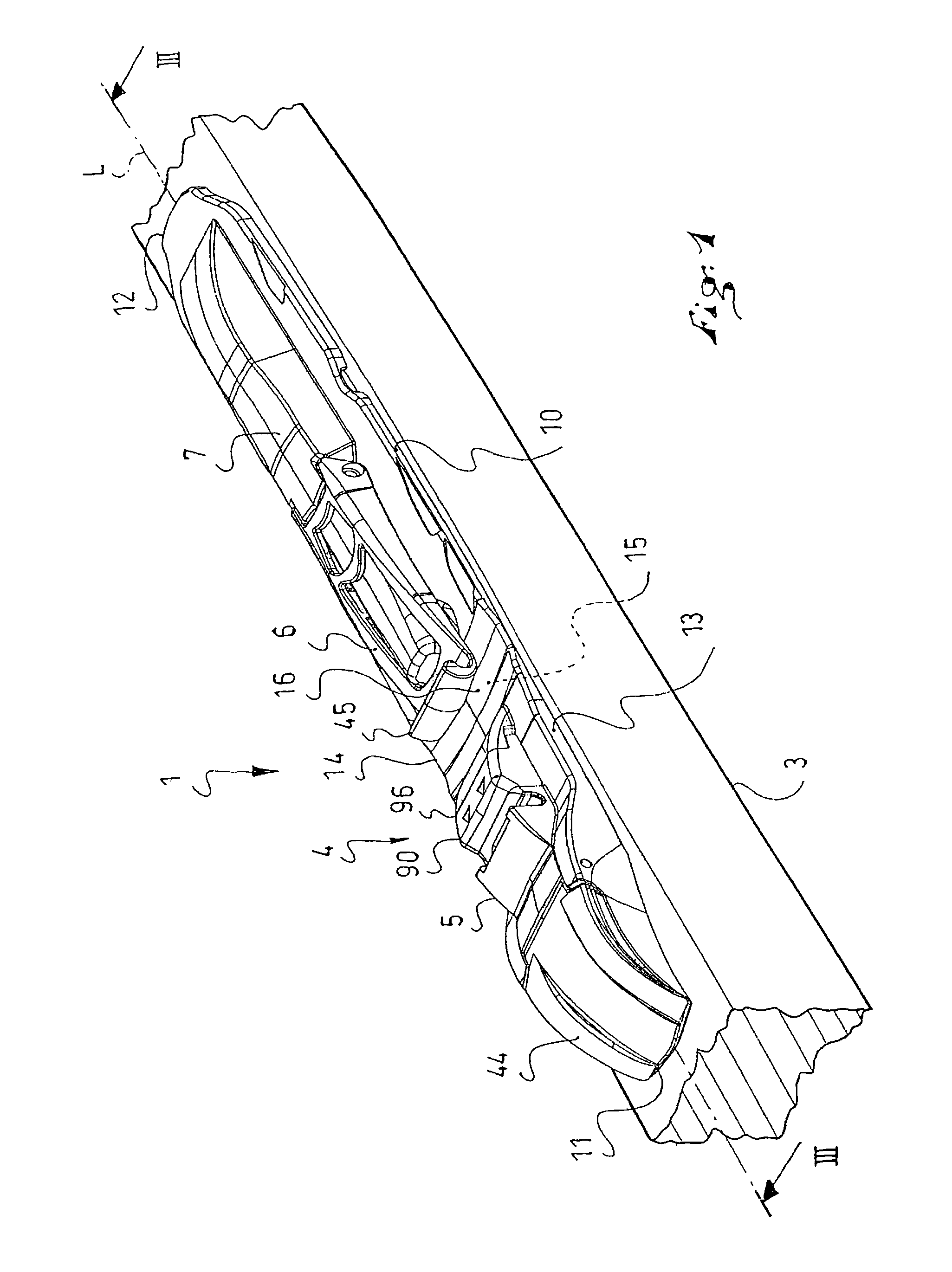
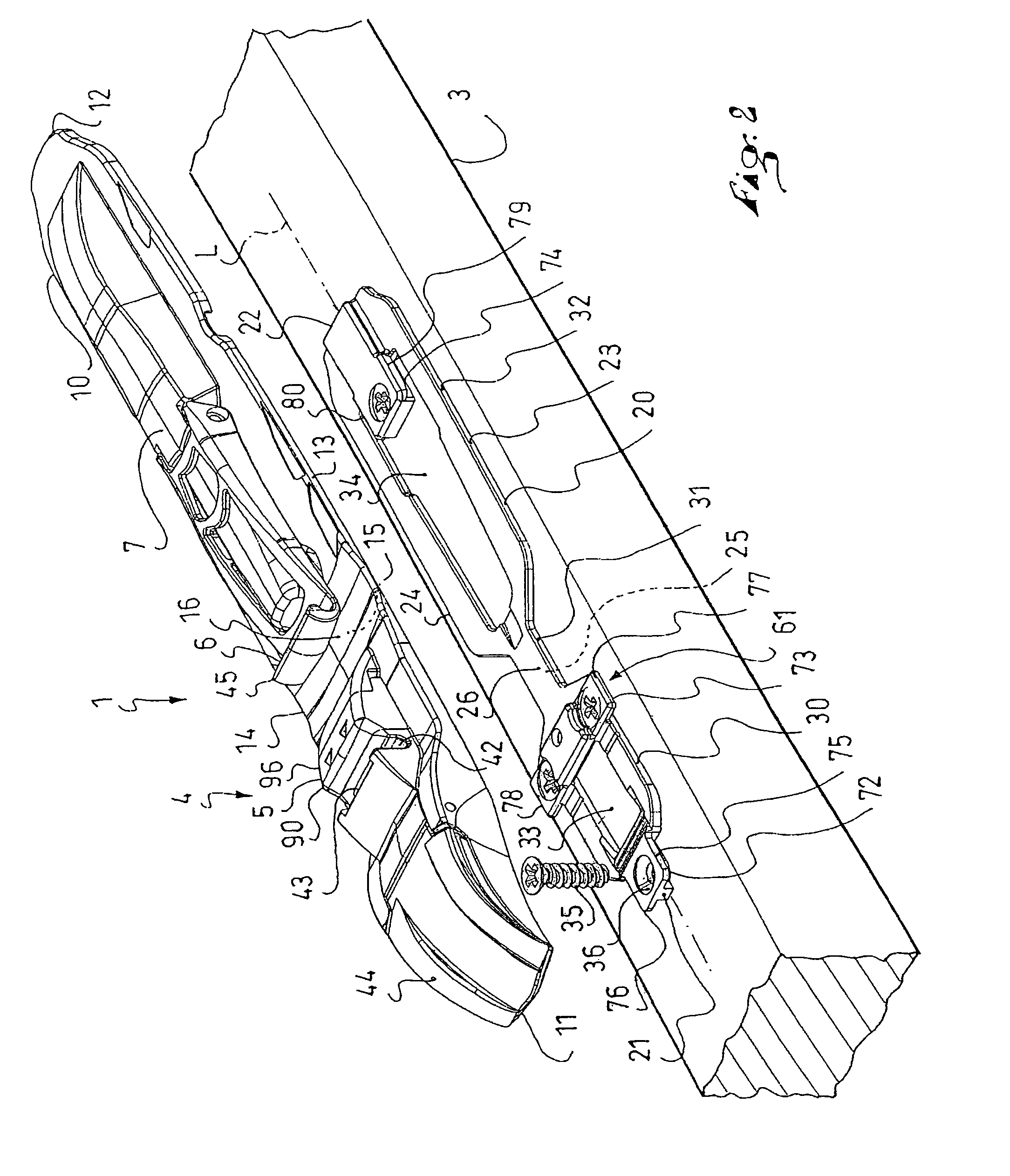
[0024]The embodiment is illustrated in FIGS. 1 to 6.

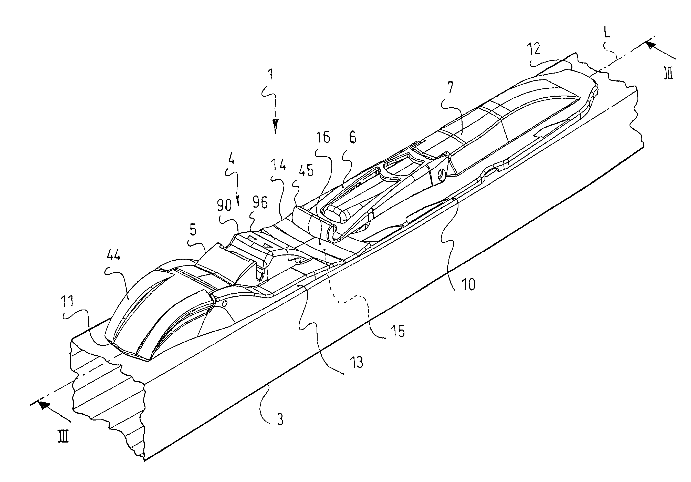
[0025]As can be understood by means of FIGS. 1-3, an assembly 1 enables a boot 2 to be retained on a gliding board 3 by means of a removable retaining device 4.

[0026]The boot 2 is schematically shown in phantom lines in FIG. 3. The board 3, i.e., the ski in the illustrated embodiment, of FIG. 1 is only partially illustrated in the drawing figures. The illustrated board 3 is a cross-country ski adapted for cross-country skiing. Such skiing involves steering the ski 3 with movements that include successive acts of lifting and lowering the heel of the boot.

[0027]The device 4 for retaining the boot 2 is any of such devices that are known to one having ordinary skill in the art.

[0028]According to the embodiment illustrated and described her...


PUM


Abstract

An assembly including a plate, a base, and a device for removably attaching the plate to the base. The plate is adapted to be associated with a device for removably retaining a boot, the base is adapted to be associated with a gliding board, such as a ski, the device for removably attaching the plate to the base including an arrangement for longitudinally guiding the plate with respect to the base. An immobilization mechanism is manually actuated to immobilize the plate with respect to the base along the longitudinal guiding direction.

Description

CROSS-REFERENCE TO RELATED APPLICATION[0001]This application claims priority under 35 U.S.C. §119 of French Patent Application No. 07 01036, filed on Feb. 13, 2007, the disclosure of which is hereby incorporated by reference thereto in its entirety.BACKGROUND OF THE INVENTION[0002]1. Field of the Invention[0003]The invention relates to the field of assemblies that include a device for removably affixing a plate to a base. More specifically, the invention relates to a device for affixing a device for retaining a boot on a gliding board. In a particular embodiment, the invention relates to a device for affixing a binding to a ski, such as for cross-country skiing.[0004]2. Description of Background and Other Information[0005]Devices of the aforementioned type are used to practice sports, such as cross-country skiing, telemark skiing, ski touring, or the like.[0006]It is known to associate a plate with a boot-retaining device, such as a binding, and to associate a base with a gliding bo...

Claims


Application Information

Patent Timeline
Patent Type & Authority Patents(United States)
IPC IPC(8): A63C9/00A63C9/086A63C9/20
CPCA63C9/20A63C9/086A63C2009/008A63C2201/06
Inventor GIRARD, FRANCOISYELOVINA, EDDY
Owner SALOMON SA
Why Eureka
Try Eureka