Electronic component device and method for manufacturing the same

a technology of electronic components and components, applied in piezoelectric/electrostrictive/magnetostrictive devices, piezoelectric/electrostrictive/magnetostriction machines, mechanical vibration separation, etc., can solve the problems of increased parts count, low vibration transmission efficiency, mechanical vibration loss in support members and casings, etc., to achieve high productivity, reduce parts count, and enhance vibration transmission efficiency

Active Publication Date: 2012-08-21
MURATA MFG CO LTD
View PDF19 Cites 9 Cited by
  • Summary
  • Abstract
  • Description
  • Claims
  • Application Information

AI Technical Summary

Benefits of technology

[0008]It is an object of the present invention to provide a vibratory device having a low parts count and achieving high vibration transmission efficiency.
[0013]According to still another specific aspect of the present invention, the piezoelectric diaphragm may include a pair of electrodes and a piezoelectric body sandwiched between the pair of electrodes, and the vibratory device may further include a driving circuit for the piezoelectric diaphragm, the driving circuit being electrically coupled to each of the electrodes, the driving circuit being arranged on the fixation member so as to overlap the piezoelectric diaphragm and so as not to overlap the fixable portion in the direction normal to the surface of the vibratory portion adjacent to the fixable portion. With this, the packaging area of the vibratory device can be reduced.
[0015]For the vibratory device according to the present invention, because the piezoelectric diaphragm is disposed on the vibratory portion of the single elastic plate including the fixable portion fixed to the fixation member, the vibratory portion, and the connection portion, its parts count can be reduced, and vibration transmission efficiency can be enhanced. Because in the direction normal to the surface of the vibratory portion adjacent to the fixable portion, at least part of the piezoelectric diaphragm does not overlap the fixable portion, the piezoelectric diaphragm can be readily attached. Accordingly, high productivity can be achieved.

Problems solved by technology

However, because the vibratory devices 100 and 110 need a support member and a housing, the problem of an increased parts count is present.
In addition, because vibration occurring in each of the vibratory devices 100 and 110 is transmitted through the support member and casing, mechanical losses of vibration occur in the support member and casing and the vibration transmission efficiency is low.

Method used


Image

  • Electronic component device and method for manufacturing the same
  • Electronic component device and method for manufacturing the same
  • Electronic component device and method for manufacturing the same

Examples


first embodiment

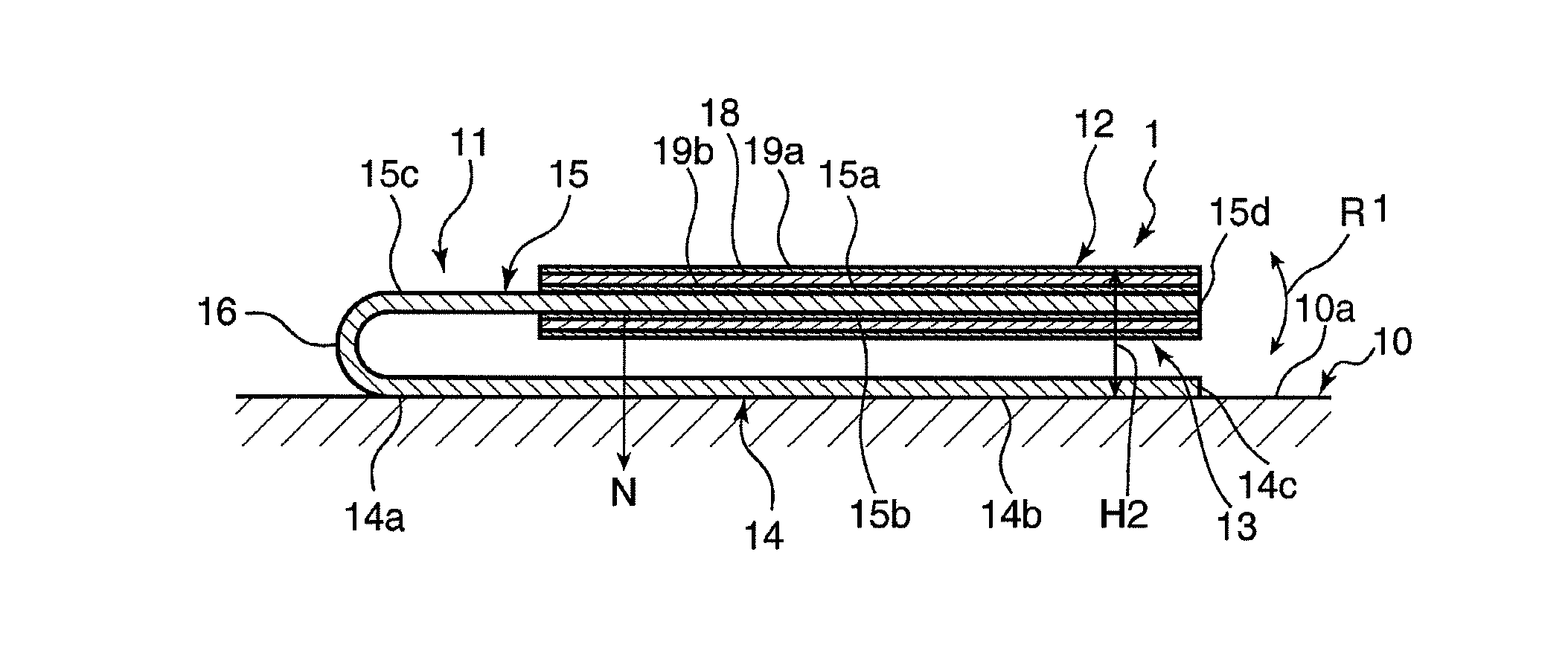
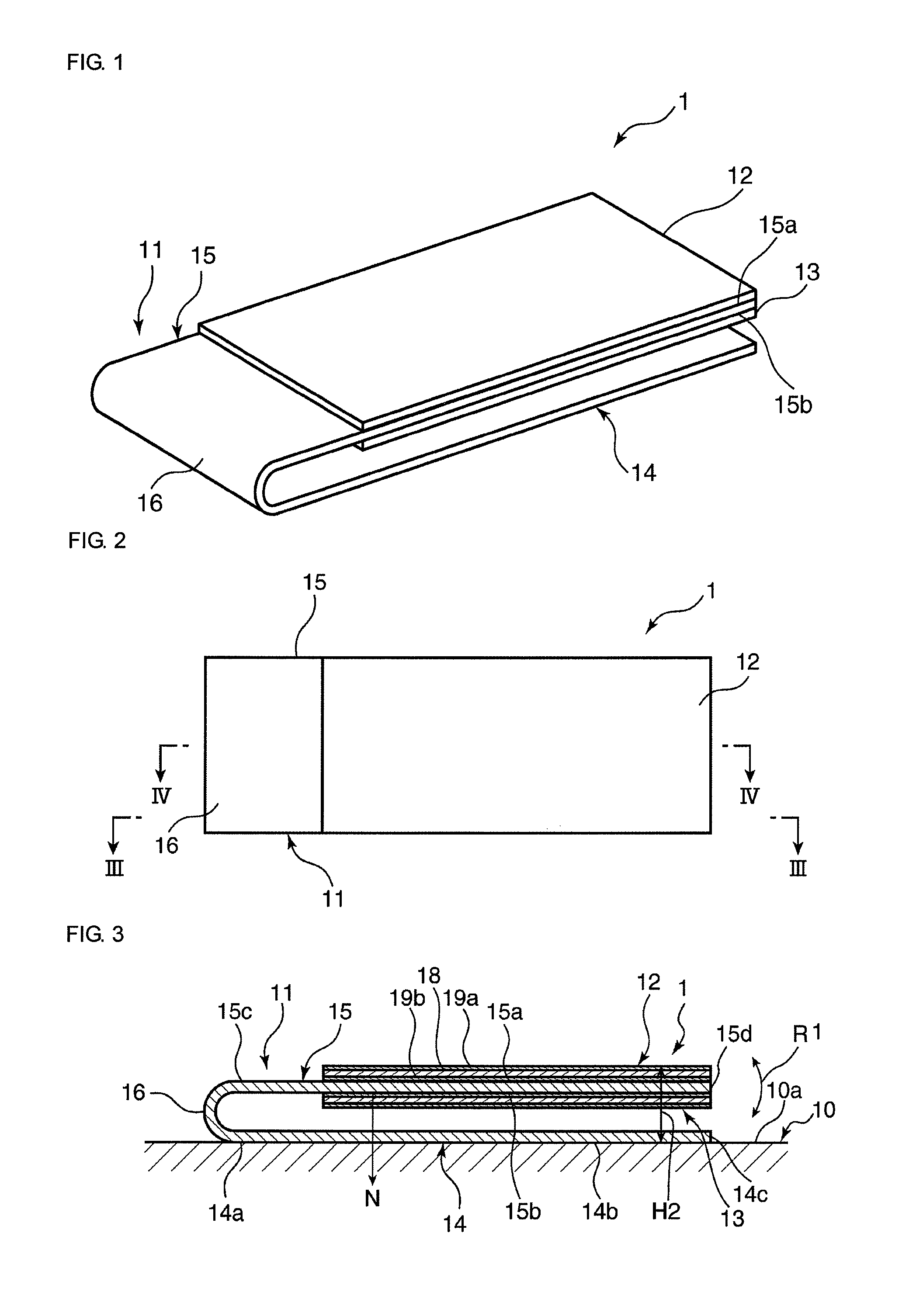
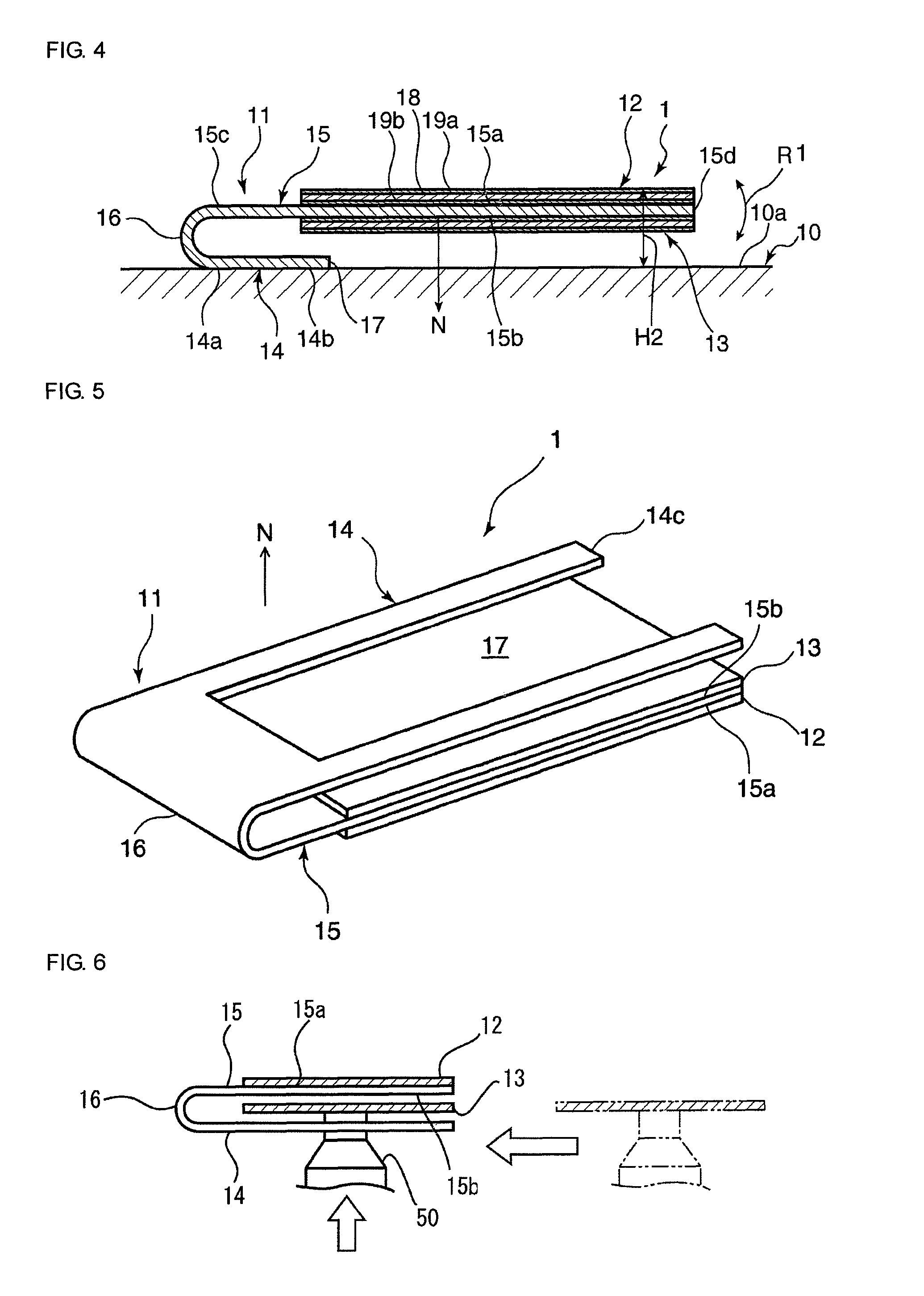
[0042]FIG. 1 is a schematic perspective view of a vibratory device 1 of the present embodiment. FIG. 2 is a schematic plan view of the vibratory device 1. FIG. 3 is a schematic cross-sectional view of the vibratory device 1 along the cut line III-III illustrated in FIG. 2. FIG. 4 is a schematic cross-sectional view of the vibratory device 1 along the cut line IV-IV illustrated in FIG. 2.

[0043]As illustrated in FIG. 3, the vibratory device 1 is a device fixed to a fixation member 10 and used for transmitting vibration to the fixation member 10. The fixation member 10 is not particularly limited. The fixation member 10 can be a casing of a cellular phone, for example. That is, the vibratory device 1 can be used in a vibrator of a cellular phone, for example.

[0044]As illustrated in FIG. 1, the vibratory device 1 includes an elastic plate 11, a first piezoelectric diaphragm 12, and a second piezoelectric diaphragm 13. The elastic plate 11 includes integrally formed plate-like fixable po...

second embodiment

[0067]For the above first embodiment, an example in which the cut portion 17 of the fixable portion 14 forms a section that does not overlap the fixable portion 14 in the second piezoelectric diaphragm 13 in the normal direction N is described. However, the present invention is not limited to this configuration.

[0068]For example, as illustrated in FIG. 7, the second piezoelectric diaphragm 13 may include a section that does not overlap the fixable portion 14 in the normal direction N by making the length L1 between the first end of the fixable portion 14 in its planar direction, the end being adjacent to the connection portion 16, and the second end 14c shorter than the length L2 between the first end of the vibratory portion 15 in its planar direction, the end being adjacent to the connection portion 16, and the second end 15d. Even in this case, the mounting nozzle 50 can be positioned in the normal direction N of the vibratory portion 15. Thus, the second piezoelectric diaphragm ...

third embodiment

[0077]FIG. 14 is a schematic cross-sectional view of a vibratory device 1c of a third embodiment. FIG. 15 is an illustration taken along the line XV-XV in FIG. 14. As illustrated in FIG. 15, for the present embodiment, the fixable portion 14 is fixed to the fixation surface 10a of the fixation member 10 such that a flexible printed board 51 attached to the fixable surface 14b is disposed therebetween. As illustrated in FIG. 15, the flexible printed board 51 is provided with a driving circuit 52 for the first and second piezoelectric diaphragms 12 and 13, the driving circuit 52 being electrically coupled to the electrodes 19a and 19b. The driving circuit 52 is positioned within the cut portion 17. The driving circuit 52 is fixed on the fixation member 10 so as to overlap the second piezoelectric diaphragm 13 and so as not to overlap the fixable portion 14 in the normal direction N.

[0078]In this way, arranging the driving circuit 52 so as to overlap the second piezoelectric diaphragm ...


PUM


Abstract

A vibratory device includes an elastic plate and a piezoelectric diaphragm. The elastic plate includes a fixable portion, a vibratory portion, and a connection portion. The fixable portion is fixed to a fixation member. The vibratory portion is spaced away from a fixable surface of the fixable portion that faces the fixation member and arranged substantially in parallel with the fixable surface. The connection portion connects a first end of the fixable portion in its planar direction and a first end of the vibratory portion in its planar direction. The piezoelectric diaphragm is disposed on a surface of the vibratory portion that is adjacent to the fixable portion. In a direction N normal to the surface of the vibratory portion adjacent to the fixable portion, at least part of the second piezoelectric diaphragm does not overlap the fixable portion.

Description

CROSS REFERENCE TO RELATED APPLICATIONS[0001]The present application is a continuation of International Application No. PCT / JP2009 / 003029, filed Jun. 30, 2009, which claims priority to Japanese Patent Application No. JP2008-218624, filed Aug. 27, 2008, the entire contents of each of these applications being incorporated herein by reference in their entirety.FIELD OF THE INVENTION[0002]The present invention relates to a vibratory device and, in particular, a vibratory device including an elastic plate to which a piezoelectric vibrator is attached.BACKGROUND OF THE INVENTION[0003]Various vibratory devices are proposed as a vibratory device for use in indicating the arrival of an incoming call by vibration. For example, Patent Literature 1 listed below discloses one such example vibratory device. FIG. 23 is a plan view of the vibratory device disclosed in Patent Literature 1. As illustrated in FIG. 23, for a vibratory device 100 disclosed in Patent Literature 1, a ceramic vibrator 105 ...

Claims


Application Information

Patent Timeline
Patent Type & Authority Patents(United States)
IPC IPC(8): H01L41/08
CPCB06B1/0603
Inventor KAGAYAMA, KENJIUNAMI, TOSHIHIKO
Owner MURATA MFG CO LTD
Why Eureka
Try Eureka