Autoinjector

An automatic injector and syringe technology, which is applied in the directions of automatic injectors, syringes, hypodermic injection devices, etc., can solve the problems of pushing buttons/plungers, and achieve the effect of reducing production costs.

Active Publication Date: 2016-05-11
SANOFI AVENTIS DEUT GMBH
View PDF7 Cites 3 Cited by
  • Summary
  • Abstract
  • Description
  • Claims
  • Application Information

AI Technical Summary

Problems solved by technology

Also, the force required to push the button / plunger may be too high (for example, if the user is an elderly person or a child)
Also, aligning the injection device, administering the injection, and holding the injection device still during the injection can require dexterity that some patients (e.g., elderly patients, children, arthritic patients, etc.) may not possess.

Method used


Image

  • Autoinjector
  • Autoinjector
  • Autoinjector

Examples


Embodiment Construction

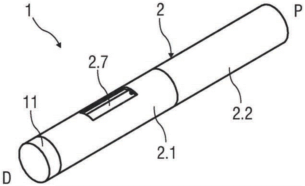
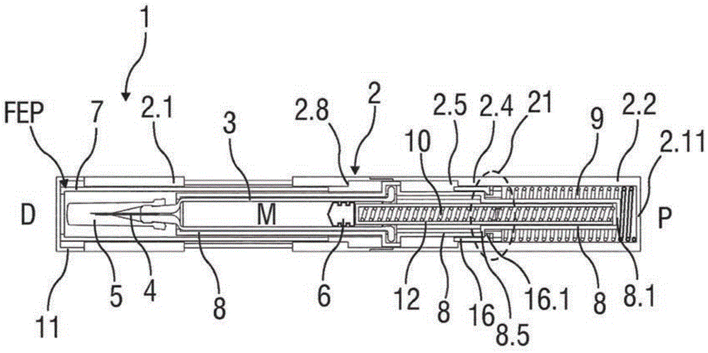
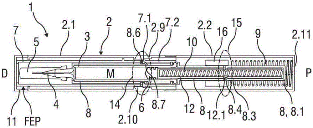
[0031] Figure 1A is a perspective view of an exemplary embodiment of an autoinjector 1 comprising a housing 2 and a cap 11 prior to use. Figure 1B and 1C is a longitudinal section of the autoinjector 1 before use.

[0032] In an exemplary embodiment, the housing 2 of the autoinjector 1 comprises a distal housing 2.1 and a proximal housing 2.2, the distal housing 2.1 being coupled with the proximal housing 2.2 during assembly. A cover 11 is detachably coupled to the distal end of the housing 2 . The housing 2 comprises a viewing window 2.7, which may be a hole in the housing 2 or a transparent part.

[0033] The housing 2 is adapted to hold a syringe 3 containing a medicament. The syringe 3 may be a prefilled syringe and has a needle 4 arranged at the distal end. In another exemplary embodiment, the syringe 3 may be a medicament cartridge adapted to removably receive the needle 4 (eg, by snap fit, friction, threads, etc.). A protective needle sheath 5 may be removably at...


PUM


Abstract

Described is an autoinjector (1) comprising a case (2), a syringe carrier (8) slidably disposed within the case (2) and adapted to hold a syringe (3) including a stopper (6), a plunger (12) slidably disposed within the syringe carrier (8) and adapted to apply a force on the stopper (6), and a drive spring (10) disposed within the plunger (12) and biasing the plunger (12) relative to the syringe carrier (8).

Description

technical field [0001] The present invention relates to automatic injectors. Background technique [0002] The process of administering an injection presents various risks and challenges to both the user and the healthcare professional, both mentally and physically. Injection devices typically fall into two types—manual devices and autoinjectors. In conventional manual devices, manual force is required to drive the medicament through the needle. This is typically done with some type of button / plunger which must be continuously depressed during the injection. This solution has several drawbacks. For example, if the button / plunger is released too early, the injection will stop and it will not be possible to deliver the intended dose. Also, the force required to push the button / plunger may be too high (eg, if the user is an elderly person or a child). Also, aligning the injection device, administering the injection, and holding the injection device still during the injecti...

Claims


Application Information

Patent Timeline
Patent Type & Authority Applications(China)
IPC IPC(8): A61M5/20A61M5/32
CPCA61M5/2033A61M5/3204A61M5/326A61M5/5086A61M2005/2013A61M2005/206A61M2005/208A61M2005/3247A61M2205/581A61M2205/582A61M2205/584
Inventor T·肯普特
Owner SANOFI AVENTIS DEUT GMBH
Why Eureka
Try Eureka