Auto-injector

a technology of auto-injector and injection tube, which is applied in the direction of intravenous device, infusion needle, other medical devices, etc., can solve the problems of user delivery an underdose, injection force may be too high for the user, and the risk of users and healthcare professionals, so as to reduce the travel of the syringe and the overall length, prevent the injury of the needle stick, and increase the safety of the needl

Active Publication Date: 2014-11-04
SANOFI AVENTIS DEUT GMBH
View PDF8 Cites 4 Cited by
  • Summary
  • Abstract
  • Description
  • Claims
  • Application Information

AI Technical Summary

Benefits of technology

[0033]The auto-injector according to the invention has a particularly low part count compared to most conventional auto-injectors. The use of just one compression spring reduces the amount of metal needed and thus consequently reduces weight and manufacturing costs.
[0049]A decoupling carrier may be slidably arranged in the retraction sleeve and coupled to the syringe for joint axial translation. The decoupling carrier comprises at least one second resilient clip engageable in a detent in or behind a shoulder on the plunger in a manner to lock the decoupling carrier to the plunger for joint axial translation. The retraction sleeve is arranged for outwardly supporting the second resilient clip prior to the syringe reaching an injection depth during needle insertion. A respective aperture for each second resilient clip is arranged in the retraction sleeve allowing the second resilient clip to be flexed outwards and disengage from the detent upon the syringe reaching the injection depth thus coupling the plunger to the stopper. Consequently, a so called wet injection is avoided, i.e. the liquid medicament is not leaking out of the hollow needle before the needle is inserted.

Problems solved by technology

Administering an injection is a process which presents a number of risks and challenges for users and healthcare professionals, both mental and physical.
There are numerous disadvantages to the user from this approach.
This means that the user can deliver an underdose if the device is not used properly (i.e. the plunger is not fully pressed to its end position).
Injection forces may be too high for the user, in particular if the patient is elderly or has dexterity problems.
The extension of the button / plunger may be too great.
Thus it can be inconvenient for the user to reach a fully extended button.
The combination of injection force and button extension can cause trembling / shaking of the hand which in turn increases discomfort as the inserted needle moves.
Consequently the plunger is no longer pushed in proximal direction and does not prevent retraction of the syringe and needle, so they can be retracted along with the plunger.

Method used


Image

  • Auto-injector
  • Auto-injector
  • Auto-injector

Examples


Embodiment Construction

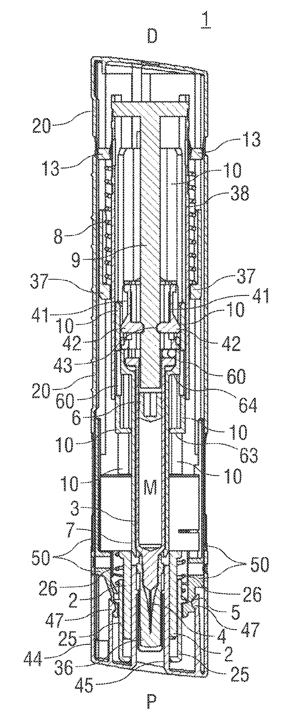
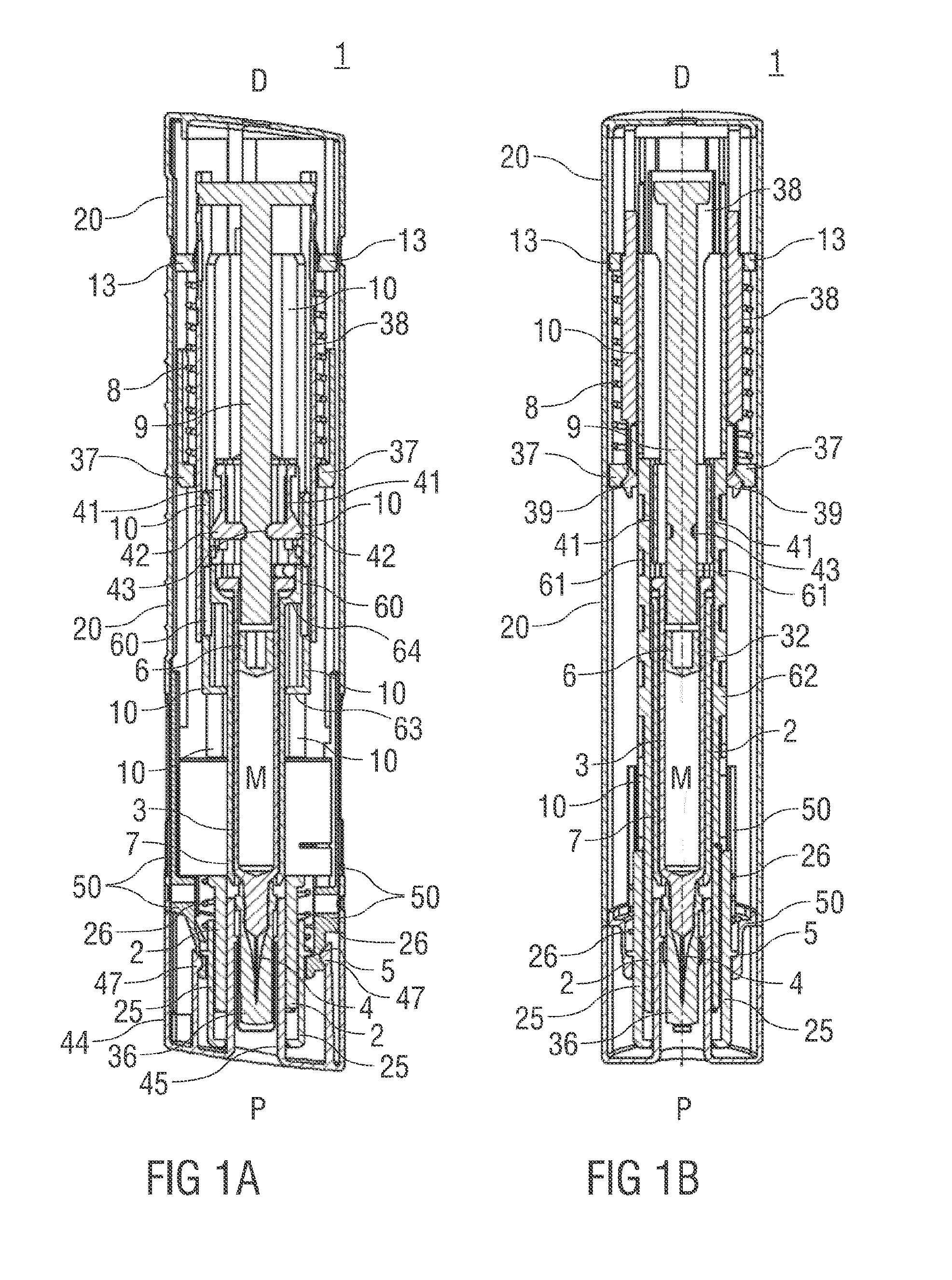
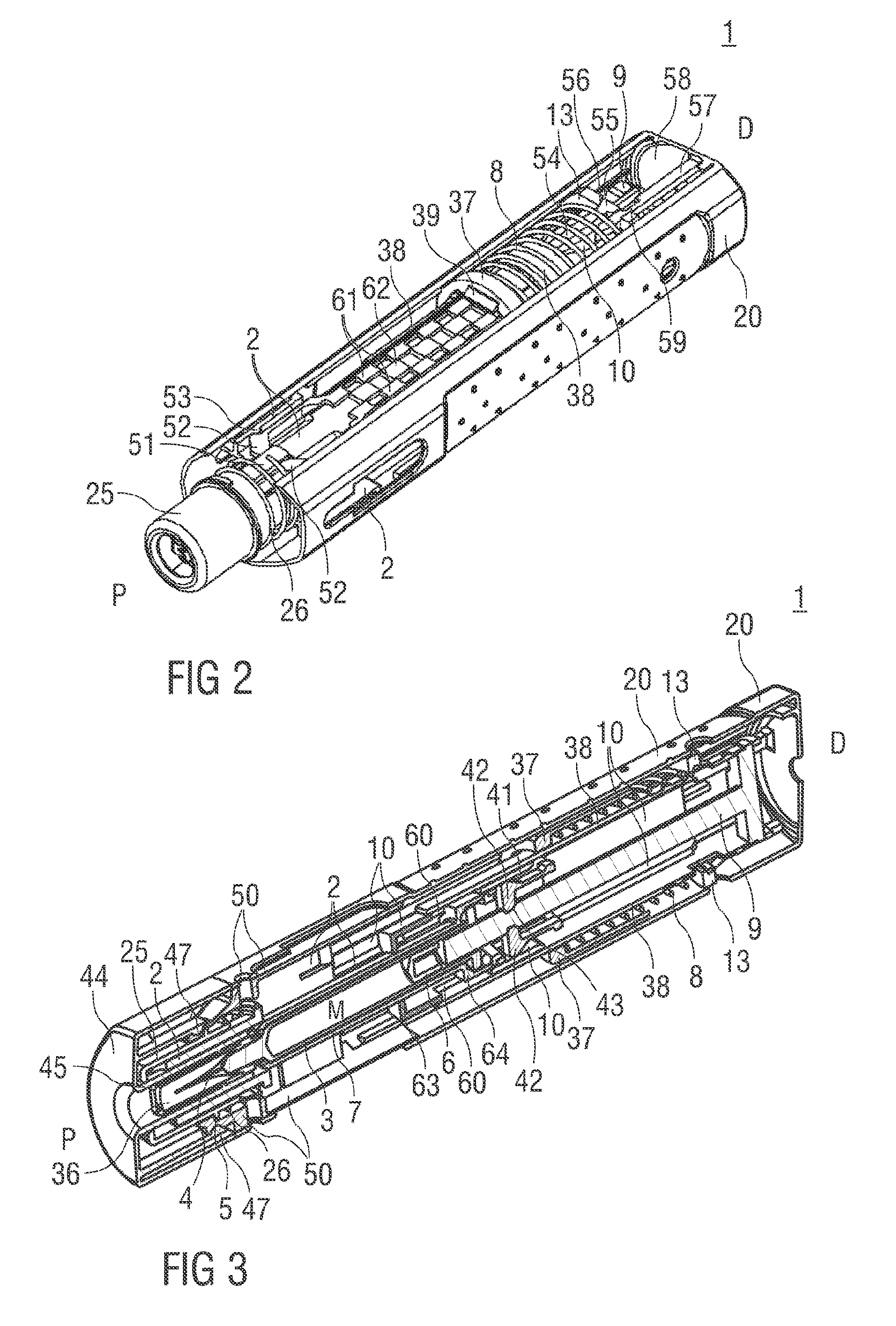
[0078]FIGS. 1A and 1B show two longitudinal sections in different section planes of an auto-injector 1, the different section planes approximately 90° rotated to each other. The auto-injector 1 comprises a chassis 2. A syringe 3, e.g. a Hypak syringe, with a hollow needle 4 is arranged in a proximal part of the auto-injector 1. When the auto-injector 1 or the syringe 3 is assembled a protective needle shield 36 is attached to the needle 4. A stopper 6 is arranged for sealing the syringe 3 distally and for displacing a liquid medicament M through the hollow needle 4. The syringe 3 is held in a tubular syringe carrier 7 and supported at its proximal end therein. The syringe carrier 7 is slidably arranged in the chassis 2. A single drive spring 8 in the shape of a compression spring is arranged in a distal part of the auto-injector 1.

[0079]The drive spring 8 is loaded between a retraction sleeve 10 and a thrust collar 37. A plunger 9 for forwarding the spring force of the drive spring ...


PUM


Abstract

The invention refers to an auto-injector for administering a medicament (M), comprising of a chassis, a syringe with a hollow needle and a stopper; a drive spring capable of, upon activation: advancing the needle (3), injecting the medicament (M), and retracting the syringe with the needle after delivering the medicament (M); and; activating means arranged to lock and release the drive spring, wherein the drive spring is a compression spring arranged to be grounded at a distal end in the chassis for advancing the needle and for injecting the dose of medicament (M) via a plunger and wherein the drive spring is arranged to have its ground in the chassis switched to its proximal end for retracting the syringe. A refraction sleeve is axially movable arranged around the syringe, wherein the retraction sleeve is fixable in a maximum proximal position for providing ground at the distal end of the drive spring, wherein the retraction sleeve is arranged to take the syringe with it when released and translated in distal direction (D), wherein the compression spring is wrapped over the retraction sleeve with its distal end bearing against a thrust face on the retraction sleeve and with its proximal end bearing against a thrust collar arranged to be coupled to the plunger for joint axial translation for advancing the needle and for injecting the dose of medicament (M) and to decouple from the plunger for retraction.

Description

CROSS REFERENCE TO RELATED APPLICATIONS[0001]The present application is a U.S. National Phase Application pursuant to 35 U.S.C. §371 of International Application No. PCT / EP2011 / 067502 filed Oct. 6, 2011, which claims priority to European Patent Application No. 10187008.7 filed Oct. 8, 2010 and U.S. Provisional Patent Application No. 61 / 432,257 filed Jan. 13, 2011. The entire disclosure contents of these applications are herewith incorporated by reference into the present application.TECHNICAL FIELD[0002]The invention relates to an auto-injector for administering a dose of a liquid medicament according to the preamble of claim 1.BACKGROUND[0003]Administering an injection is a process which presents a number of risks and challenges for users and healthcare professionals, both mental and physical.[0004]Injection devices (i.e. devices capable of delivering medicaments from a medication container) typically fall into two categories—manual devices and auto-injectors.[0005]In a manual devi...

Claims


Application Information

Patent Timeline
Patent Type & Authority Patents(United States)
IPC IPC(8): A61M5/32A61M5/315A61M5/20
CPCA61M5/3158A61M2005/208A61M5/326A61M5/3204A61M2205/581A61M2005/2013A61M2005/206A61M5/2033A61M2205/582A61M5/3202
Inventor HOURMAND, YANNICKBRERETON, SIMON FRANCISKEMP, THOMASBURNELL, ROSIEEKMAN, MATTHEW
Owner SANOFI AVENTIS DEUT GMBH
Why Eureka
Try Eureka