Cutting unit mounting device

a mounting device and cutting unit technology, applied in the direction of rod connection, fastening means, agriculture tools and machines, etc., can solve the problems of high parts count, time-consuming and costly steps, and high cost of each step, so as to reduce cost and complexity, minimize cost and assembly time, and reduce the effect of cost and complexity

Active Publication Date: 2012-12-27
DEERE & CO
View PDF7 Cites 0 Cited by
  • Summary
  • Abstract
  • Description
  • Claims
  • Application Information

AI Technical Summary

Benefits of technology

[0008]The cutting unit mounting device reduces cost and complexity, and has a low parts count, so that it can minimize cost and assembly time of the grass mowing machine. The mounting device allows the cutting unit to pitch, yaw and steer during mowing, and allows the cutting unit to be easily mov

Problems solved by technology

Existing cutting unit mounting devices are relatively expensive and complex, and have a relatively high parts count, which can contribute to the cost and assembly time of the grass mowing machine

Method used


Image

  • Cutting unit mounting device
  • Cutting unit mounting device
  • Cutting unit mounting device

Examples


first embodiment

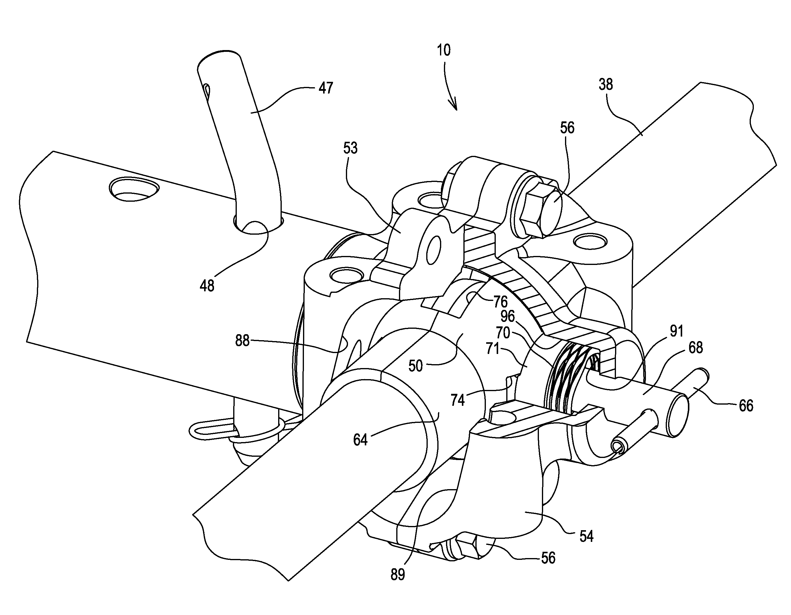
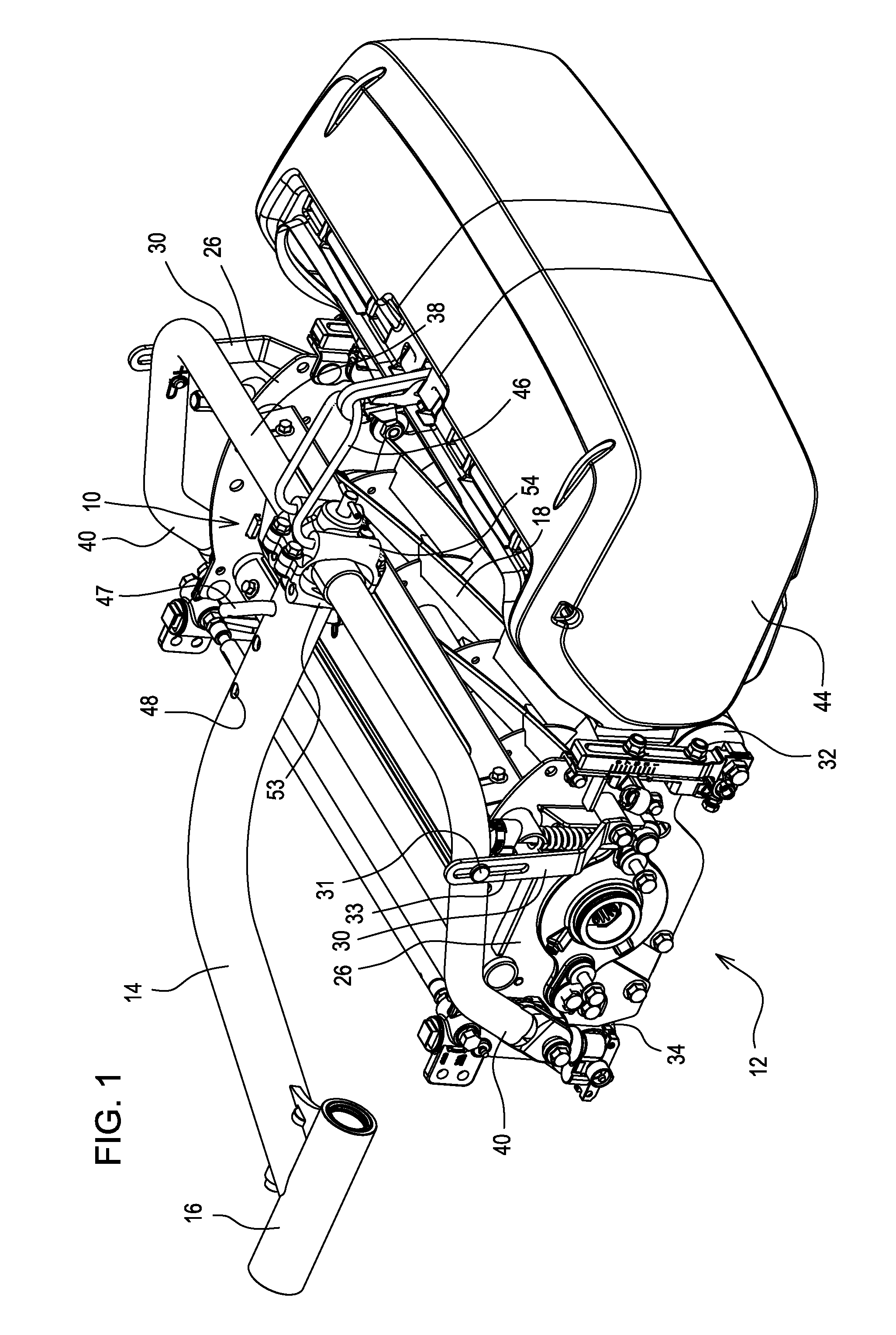
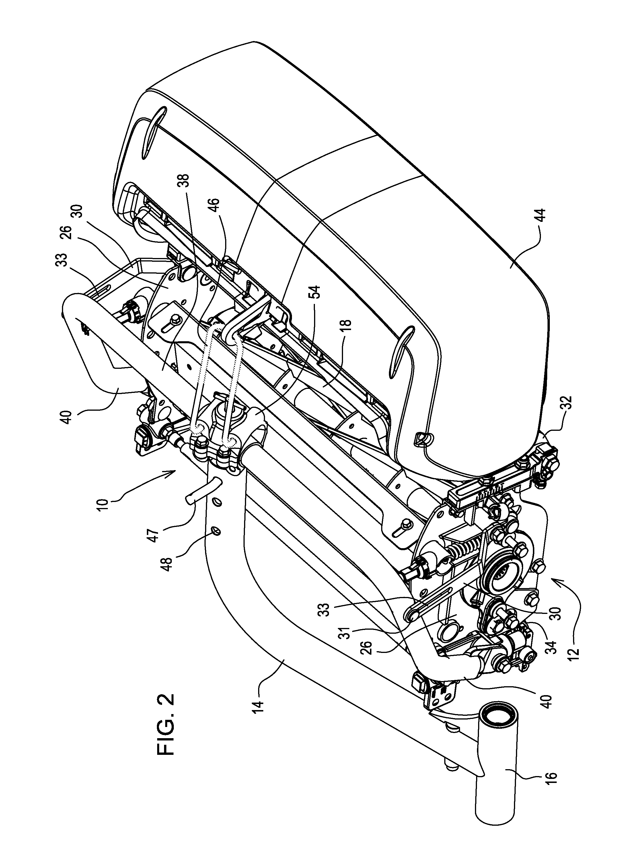
[0017]As shown in FIG. 1, in a first embodiment, cutting unit mounting device 10 may be used to mount cutting unit 12 to a grass mowing machine. In the mowing position, the cutting unit mounting device allows the cutting unit to follow ground contours, pivoting on three axes as the cutting unit is pushed across the turf. A single cutting unit mounting device may be provided for a single cutting unit on a grass mowing machine, or multiple cutting unit mounting devices may be provided for multiple cutting units. Three, five or more cutting units may be mounted side-by-side in two rows carried by a grass mowing machine having a vehicle with traction drive. For example, each cutting unit mounting device 10 may be positioned at the end of a lift arm 14 extending laterally and / or forwardly from the grass mowing machine. The lift arm may pivot with respect to the grass mowing machine so that the cutting unit may be raised and lowered with a hydraulic or electric lift device. The lift arm a...

second embodiment

[0032]In one embodiment, pin 47 may be inserted through one of holes 48 in lift arm 14 to hold ball retainer 53 to the lift arm, in the mowing, transport or service positions. Pin 47 also may engage or be inserted through a corresponding hole in a sleeve attached to the ball retainer and that slides into the end of the lift arm. In a second embodiment shown in FIGS. 4 and 8, pivotable sleeve 62 may be attached to ball retainer 52. The pivotable sleeve may include first sleeve member 87 attached to the ball retainer, and second sleeve member 88 pivotably attached thereto. The second sleeve member may have a slot 93 that pin 47 may be inserted through. To hold the cutting unit in the mowing or transport positions, the pivotable sleeve, including both of the first and second sleeve members, may be fully inserted into the end of the lift arm. Once the pivotable sleeve is fully inserted into the lift arm, pin 47 may hold it in place by inserting the pin through hole 48 in the lift arm an...


PUM


Abstract

A cutting unit mounting device includes a ball through which a yoke extends laterally. The yoke is attached to the cutting unit, and the ball is pivotably mounted in a ball housing attached to a lift arm. A releasable lock pin engages and secures the ball within the ball housing in a mowing position or a service position. The ball housing has stops to limit the pivoting of the ball and yoke with respect to the ball housing. A releasable lock pin engages notches in the ball to engage and secure the ball in the mowing position or service position with respect to the ball housing.

Description

FIELD OF THE INVENTION[0001]The present invention relates to grass mowing machines with one or more cutting units, and specifically to a cutting unit mounting device for a grass mowing machine that allows the cutting unit to pivot during mowing, to be raised to a transport position, and rotated to a service position.BACKGROUND OF THE INVENTION[0002]Grass mowing machines used for golf courses, parks, and athletic fields where a high quality of cut is desired, may include one or more cutting units. For example, each cutting unit may be a reel mower having multiple spiral cutting blades rotating in close proximity to a bedknife. Each cutting unit may be mounted to the grass mowing machine using a cutting unit mounting device or coupling mechanism through a yoke which may be a tubular element with a crossbar that extends laterally over and is attached to the left and right sides of the cutting unit. The cutting unit mounting device may include a pivoting mechanism to allow the cutting u...

Claims


Application Information

Patent Timeline
IPC IPC(8): F16C11/10F16C11/06
CPCY10T403/32311Y10T403/125A01D34/43Y10T403/32361Y10T403/32565Y10T403/32426
Inventor PHILLIPS, DAVID LAWRENCEBUCHHEIT, MICHAEL JOSEPHJARAMILLO, JENNIFER LYNNHEIDE, PAUL ROBERT
Owner DEERE & CO
Why Eureka
Try Eureka