Method and device for detecting placement error of an imaging plane of a radiographic image detector, as well as method and device for correcting images

a radiographic image and imaging plane technology, applied in the direction of image enhancement, material analysis using wave/particle radiation, instruments, etc., can solve the problems of low accuracy of the guide mechanism for guiding the radiographic image detector being shifted, the problem of misalignment along the joint line between the images, and the generation of misalignment along the joint lin

Active Publication Date: 2012-10-30
FUJIFILM CORP
View PDF8 Cites 24 Cited by
  • Summary
  • Abstract
  • Description
  • Claims
  • Application Information

AI Technical Summary

Benefits of technology

[0030]In view of the above-described circumstances, the present invention is directed to providing an image correction method that can eliminate, through a simple operation, misalignment along a joint line between combined images due to inclination and / or displacement from a predetermined position of the two-dimensional matrix of a radiographic image detector, and a device for carrying out the method.

Problems solved by technology

There are several types of “inclination of the imaging plane” causing this problem.
The other problem here is that the two-dimensional matrix of the pixel sections may be inclined by an angle γ with respect to the axis of the shift, i.e., the one side of the panel, in a plane parallel to the surface of the panel (i.e., a plane parallel to the plane of the drawing) due to assembly error, or the like, of the radiographic image detector D. It should be noted that only some of the pixel sections G are illustrated in FIG. 11.
However, even when the two-dimensional matrix of pixel sections is not inclined within radiographic image detector, i.e., even when the matrix is formed parallel to the surface and one side of the quadrangular panel-shaped radiographic image detector, the similar problems occur when the radiographic image detector itself is inclined relative to the axis of shift of the detector. FIGS. 12 and 13 illustrate such cases where the two-dimensional matrix is inclined relative to the axis of shift of the detector by the inclination angles α and γ, respectively, since the radiographic image detector itself is inclined.
This phenomenon is due to such factors that a guide mechanism for guiding the radiographic image detector being shifted has low accuracy, or that there is a relatively large clearance between a guide rod and a guide member that slides along the guide rod, for example, forming the guide mechanism.
Further, as described above, the problem of misalignment along the joint line between the images occurs not only due to the inclination of the matrix, but also due to displacement of the matrix from a predetermined position during application of the radiation.
Actually, however, the upper end of the image taken during the second imaging operation is displaced by the length Δy, and thus misalignment is generated along the joint line.
This method, however, cannot detect the inclination and / or displacement of the two-dimensional matrix which may occur when the above-described quadrangular panel-shaped radiographic image detector is used, and thus cannot correct misalignment between the images based on such an inclination and / or displacement.

Method used


Image

  • Method and device for detecting placement error of an imaging plane of a radiographic image detector, as well as method and device for correcting images
  • Method and device for detecting placement error of an imaging plane of a radiographic image detector, as well as method and device for correcting images
  • Method and device for detecting placement error of an imaging plane of a radiographic image detector, as well as method and device for correcting images

Examples


Embodiment Construction

[0071]Hereinafter, embodiments of the present invention will be described in detail with reference to the drawings.

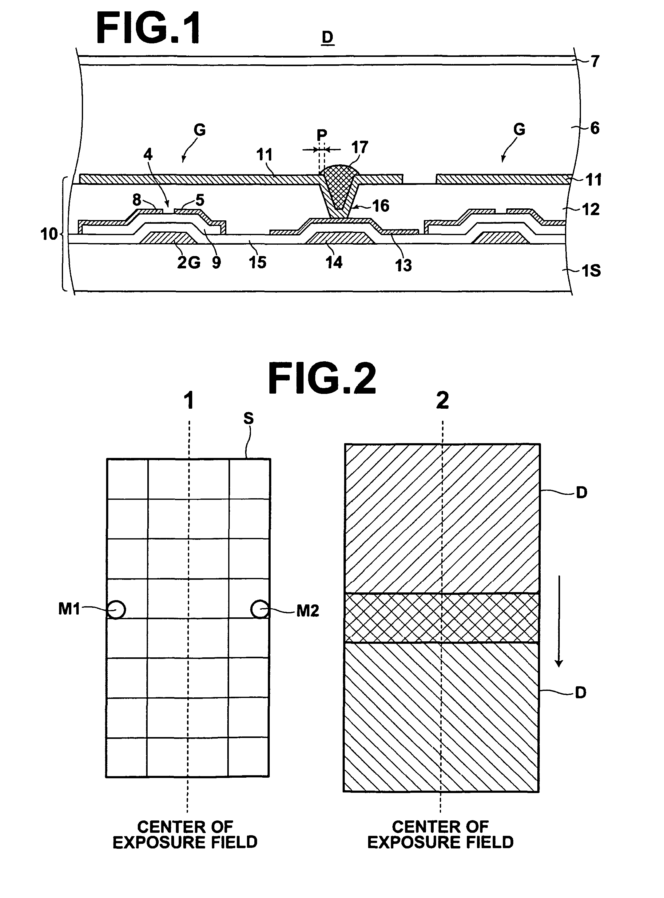
[0072]First, one example of a radiographic image detector, to which a placement error detection method for detecting placement error of an imaging plane according to the invention is applied, is described. FIG. 1 is a partial sectional view showing an area around pixel sections of such a radiographic image detector D. As shown in the drawing, the radiographic image detector D includes an active matrix substrate 10 including a number of pixel sections G, and a charge generation layer (photoelectric conversion layer) 6 having electromagnetic conductivity and a voltage application electrode (bias electrode: common electrode) 7 connected to a high voltage power supply (not shown), which are formed in this order on the active matrix substrate 10.

[0073]The pixel sections G include switching elements for reading out electric charges collected by the charge collection electrode...


PUM

PropertyMeasurementUnit
distanceaaaaaaaaaa
distanceaaaaaaaaaa
sizeaaaaaaaaaa

Abstract

For a radiographic image detector which includes an imaging plane including two-dimensional matrix of pixel sections, each pixel section storing, when exposed to radiation, a charge according to amount of the radiation, and which is used to be exposed to radiation transmitted through the same subject each time the detector is shifted along a predetermined axis of shift, an inclination of the two-dimensional matrix relative to the axis of shift of the radiographic image detector is detected. The inclination is detected by applying radiation two times to the detector at different radiation application positions effected by the shift of the detector so that a common marker is imaged during each radiation application; carrying out a reading operation after each radiation application to acquire image data representing image information of the marker; and detecting the inclination based on a positional relationship between marker images represented by the image data.

Description

CROSS-REFERENCE TO RELATED APPLICATIONS[0001]The present application claims priority from Japanese Patent Application No. 2008-236728, filed Sep. 16, 2008, and from Japanese Patent Application No. 2009-200423, filed Aug. 31, 2009, the contents of all of which are herein incorporated by reference in their entirety.BACKGROUND OF THE INVENTION[0002]1. Field of the Invention[0003]The present invention relates to a method for detecting inclination and / or displacement of an imaging plane of a radiographic image detector during recording of radiographic image information on the detector, and a device for carrying out the method.[0004]The present invention further relates to a method for applying, to image data representing a radiographic image of a subject acquired using the radiographic image detector, correction to eliminate misalignment along a joint line in a subject image which misalignment is generated when the subject image is formed by combining the image data, and a device for car...

Claims


Application Information

Patent Timeline
Patent Type & Authority Patents(United States)
IPC IPC(8): G01N23/04G06K9/38H05G1/64
CPCG06T7/0042G06T2207/30244G06T2207/30004G06T2207/10116G06T7/73
Inventor YAMAGUCHI, YOSHITAKA
Owner FUJIFILM CORP
Why Eureka
Try Eureka