Upper-bearing movable formwork for constructing continuous box girder for bridge superstructure

a technology of superstructure box girder and movable formwork, which is applied in the direction of mining structures, moulds, building parts, etc., can solve the problems of increased risk, increased structure dead weight, and operation of upper-bearing typed movable formwork, and achieves high occupation space, complicated operation of horizontal transfer mechanisms, and large dead weight

Active Publication Date: 2013-03-05
CHINA RAILWAY MAJOR BRIDGE ENG GRP CO LTD
View PDF7 Cites 5 Cited by
  • Summary
  • Abstract
  • Description
  • Claims
  • Application Information

AI Technical Summary

Benefits of technology

[0008]The technical problem to be addressed by the present invention is to solve the problem that the upper-bearing typed movable formwork has a large dead weight and a high occupation space, and the operation of the horizontal transfer mechanisms is complicated. The advantages of the invention are to utilize one energy and impetus in one direction as convenient power source so as to exert the latent energy of the generating equipment and improve the output efficiency.
[0014]In order to strengthen the rigidity of the bottom formwork, left and right bottom formwork struts are further included. An inner web plate is respectively disposed on two opposite sides of the left and right main girders, and left and right bottom formwork connecting hinge support and a bottom formwork strut connecting hinge support are respectively disposed on the inner web plate, two ends of the bottom formwork are respectively hinged with the left and right bottom formwork connecting hinge supports, and the left and right bottom formwork struts are respectively hinged with lower surfaces of the left and right bottom formworks and the bottom formwork connecting hinge supports on the inner web plate of the left and right main girders.
[0021]According to the present invention, the bottom formwork is used to replace the transverse truss (or the transverse steel box girder) and has a small dead weight, the main girder can reasonably enter the space above the concrete box girder, and the upper-bearing typed movable formwork occupies less height space below the concrete box girder, and can be adapted to lower pier shafts. With the bottom formwork, the left and right bottom formwork struts, and the finish rolled threaded steel bars A, a stable bearing system is formed, and the rigidity of the bottom formwork is utilized effectively. By reasonably arranging adjustable struts of the wing formworks and the side formworks, the stress of two web plates of the main girder is even, and thus the horizontal deformation of the girder is effectively reduced.

Problems solved by technology

(a) Large dead weight: firstly, since the formwork system is disposed on the top of the transverse truss (the transverse steel box girder), the rigidity of the formwork system cannot be fully utilized, and the transverse truss (the transverse steel box girder) needs to bear the entire load, which requires the transverse truss to have a great rigidity and a large dead weight; additionally, the deformation value of the upper-bearing typed movable formwork is a sum of the deformation values of the formwork system, the transverse truss (the transverse steel box girder), and the main girder, and thus the structure deformation is great and relatively soft, and in the condition of the same rigidity, the upper-bearing typed movable formwork needs to consume more steel.
(b) High occupation space: below the bottom surface of the concrete box girder, the height of the occupation space of the conventional upper-bearing typed movable formwork is a sum of heights of structures such as the bottom formwork system, the transverse truss (the transverse steel box girder), the main girder, the vertical and horizontal transfer system, and a landing leg; when the height of the pier shaft is close to and even smaller than the sum of the heights, the upper-bearing typed movable formwork operation is difficult, and even cannot be implemented. Low pier shafts are usually used in passenger railway bridges in China.
(c) Unreasonable structure stress: the deployment of the structural system of the conventional upper-bearing typed movable formwork determines the disadvantages that the transverse truss (the transverse steel box girder) is bent, the load of web plates at the inner and outer sides of the girder is not even, and the additional torque is great, and the structure stress is unreasonable, thus resulting in increase of the dead weight of the structures and increase of risks.
(d) Many horizontal transfer mechanisms and complicated operations: for the conventional upper-bearing typed movable formwork, the transverse truss (the transverse steel box girder) and formwork system are divided into several individual action units longitudinally, each unit is equipped with a set of horizontal transfer mechanisms, and when the upper-bearing typed movable formwork runs, the horizontal transfer mechanisms are operated respectively, so that the action units are traversed one by one. The technical solution needs many horizontal transfer mechanisms and many procedures.

Method used


Image

  • Upper-bearing movable formwork for constructing continuous box girder for bridge superstructure
  • Upper-bearing movable formwork for constructing continuous box girder for bridge superstructure
  • Upper-bearing movable formwork for constructing continuous box girder for bridge superstructure

Examples


Embodiment Construction

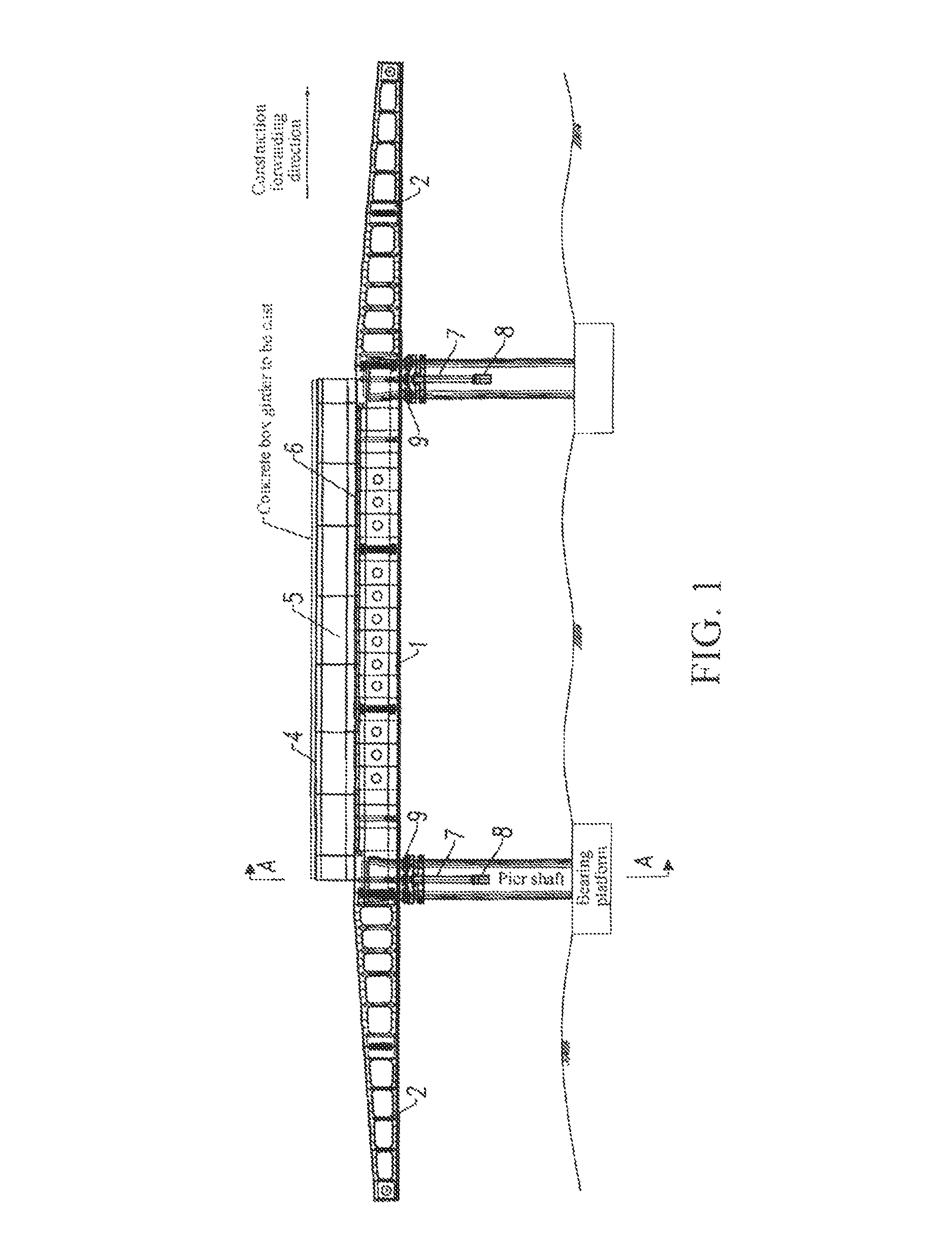
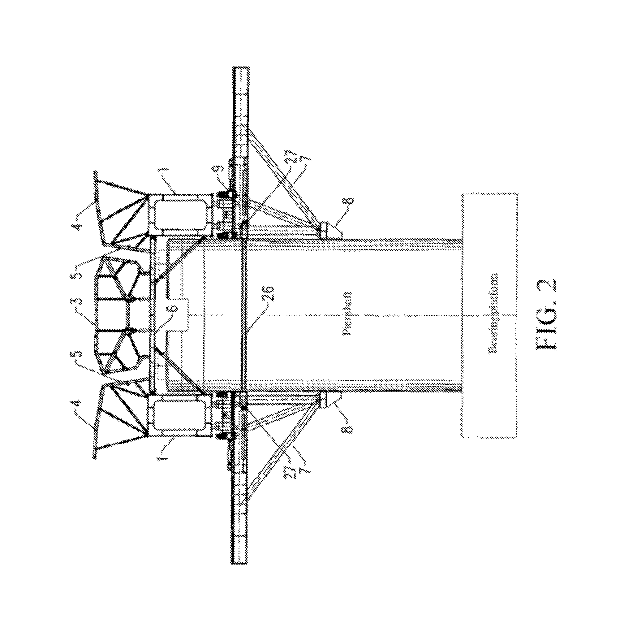
[0034]The present invention is described below in detail with reference to the accompanying drawings.

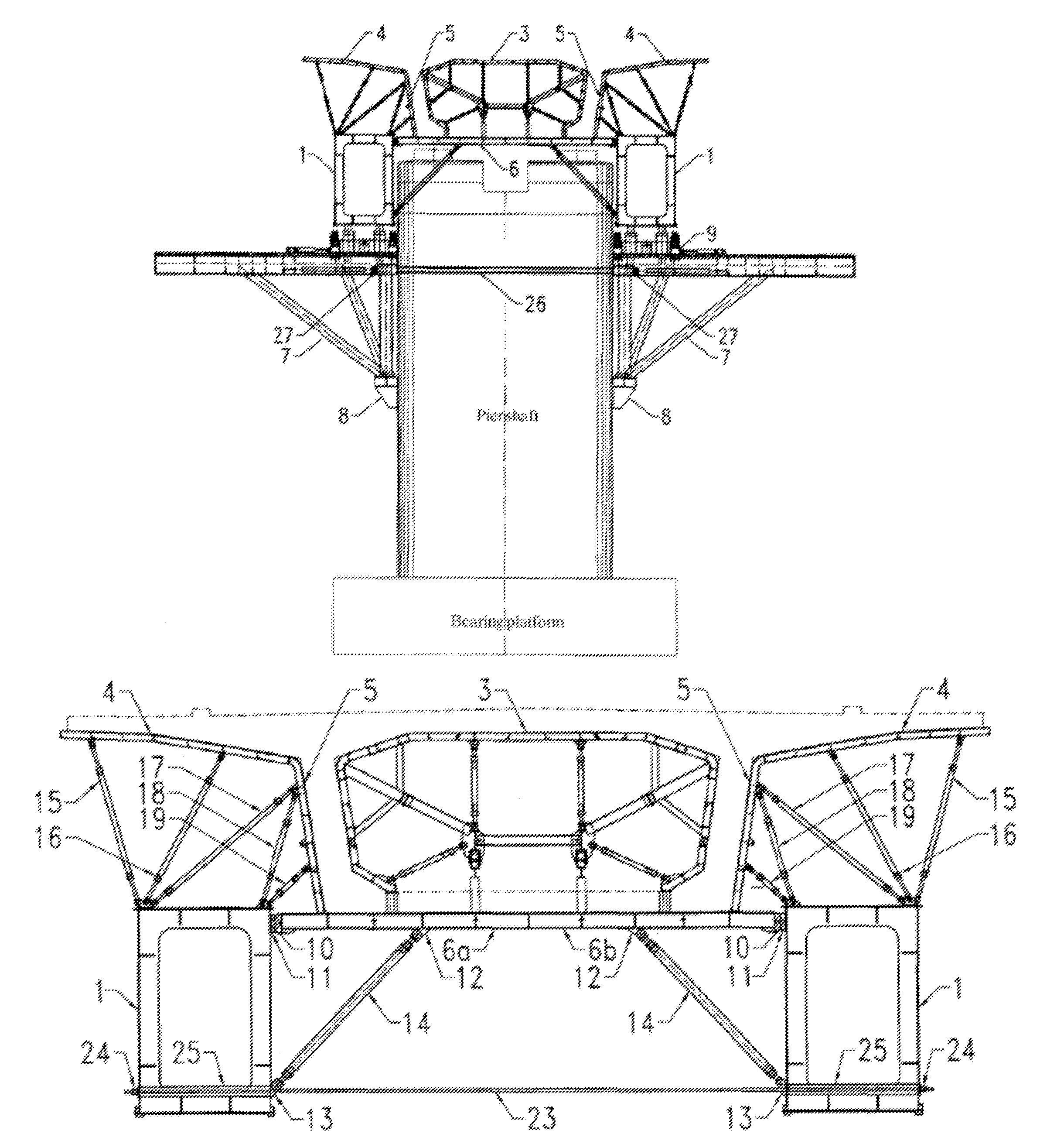
[0035]As shown in FIG. 1 and FIG. 2, the present invention includes left and right landing legs 7, left and right vertical and horizontal transfer mechanisms 9, a bearing device, and a formwork system. Left and right brackets 8 are embedded at two sides of a pier shaft. The embedded brackets 8 are installed during the construction of the pier shaft, the left and right landing legs 7 are fixedly connected to the left and right brackets 8, the landing legs 7 at two sides of the same pier shaft are fixed on the pier shaft by pulling diagonally with a finish rolled threaded steel bars B 26 and an anchorage gear B 27, and the left and right vertical and horizontal transfer mechanisms 9 are respectively disposed on the left and right landing legs 7 and move left and right along the left and right landing legs 7 horizontally.

[0036]The bearing device includes left and right main girders 1 re...


PUM


Abstract

An upper-bearing typed movable formwork used for cast-in-situ of concrete box girder in bridge engineering, comprising left and right legs (7) which are respectively fixed on a pier, left and right longitudinal / transverse sliding mechanisms (9), bearing devices and a template system. The left and right longitudinal / transverse sliding mechanisms (9) are respectively arranged on the left and right legs (7) and can move horizontally along the left and right legs (7), the bearing devices are respectively fixed on the left and right longitudinal / transverse sliding mechanisms (9), the template system comprises a bottom formwork (6), an internal formwork (3), a left formwork and a right formwork, the bottom formwork (6) is formed by screw connection of a left bottom formwork and a right bottom formwork (6a,6b) which are symmetrical about the axis line of the concrete box girder, two ends of the bottom formwork are respectively fixed on two opposite internal side surfaces of the left main beam and the right main beam (1). The movable formwork also comprises a plurality of adjustable supporting rods (14) used for supporting the template system.

Description

TECHNICAL FIELD[0001]The present invention relates to technologies of constructing a superstructure box girder in bridge engineering, and more particularly to an upper-bearing typed movable formwork used for cast-in-situ of concrete box girder.BACKGROUND OF THE INVENTION[0002]An upper-bearing typed movable formwork is construction equipment for bridge superstructure construction, and especially applicable to production of a concrete simple box girder or continuous box girder. According to different relative positions of an upper-bearing typed movable formwork main girder and the concrete box girder, the upper-bearing typed movable formwork is classified into a deck type and a through type, in which the main girder of the through upper-bearing typed movable formwork is located above the concrete box girder, and the main girder of the upper-bearing typed movable formwork is located below the concrete box girder. Compared with the through upper-bearing typed movable formwork, the upper...

Claims


Application Information

Patent Timeline
Patent Type & Authority Patents(United States)
IPC IPC(8): E04G13/00E01D21/00
CPCE01D21/00
Inventor QIN, SHUNQUANMA, TAOYAO, SENZHU, BINGUO, RONGCHUN
Owner CHINA RAILWAY MAJOR BRIDGE ENG GRP CO LTD
Why Eureka
Try Eureka