Upper-bearing typed movable formwork

Active Publication Date: 2011-06-09
CHINA RAILWAY MAJOR BRIDGE ENG GRP CO LTD
View PDF6 Cites 30 Cited by
  • Summary
  • Abstract
  • Description
  • Claims
  • Application Information

AI Technical Summary

Benefits of technology

[0008]The technical problem to be addressed by the present invention is to solve the problem that the upper-bearing typed movable formwork has a large dead weight and a high occupation space, and the operation of the horizontal transfer

Problems solved by technology

(a) Large dead weight: firstly, since the formwork system is disposed on the top of the transverse truss (the transverse steel box girder), the rigidity of the formwork system cannot be fully utilized, and the transverse truss (the transverse steel box girder) needs to bear the entire load, which requires the transverse truss to have a great rigidity and a large dead weight; additionally, the deformation value of the upper-bearing typed movable formwork is a sum of the deformation values of the formwork system, the transverse truss (the transverse steel box girder), and the main girder, and thus the structure deformation is great and relatively soft, and in the condition of the same rigidity, the upper-bearing typed movable formwork needs to consume more steel.
(b) High occupation space: below the bottom surface of the concrete box girder, the height of the occupation space of the conventional upper-bearing typed movable formwork is a sum of heights of structures such as the bottom formwork system, the transverse truss (the transverse steel box girder), the main girder, the vertical and horizontal transfer system, and a landing leg; when the height of the pier shaft is close to and even smaller than the sum of the hei

Method used


Image

  • Upper-bearing typed movable formwork
  • Upper-bearing typed movable formwork
  • Upper-bearing typed movable formwork

Examples


Embodiment Construction

[0034]The present invention is described below in detail with reference to the accompanying drawings.

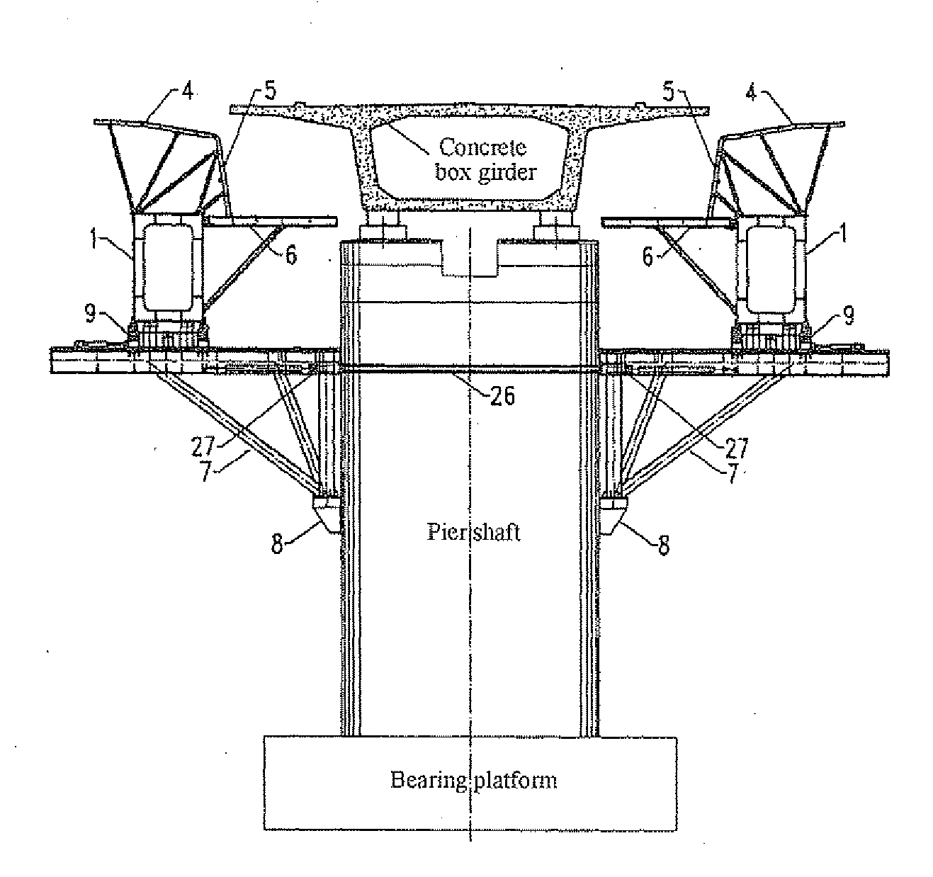
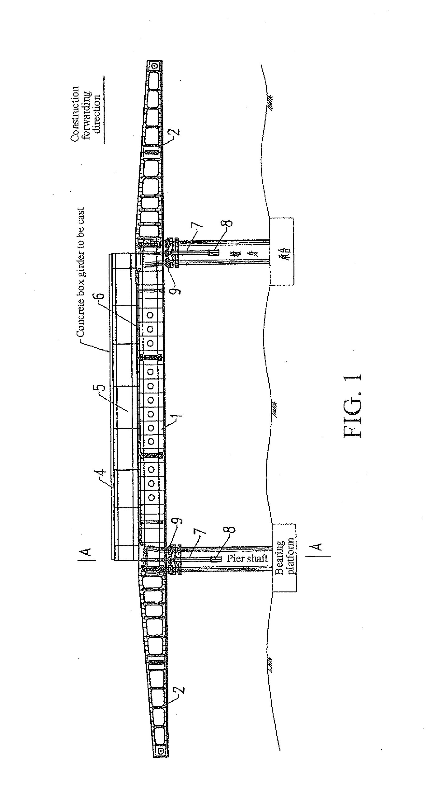
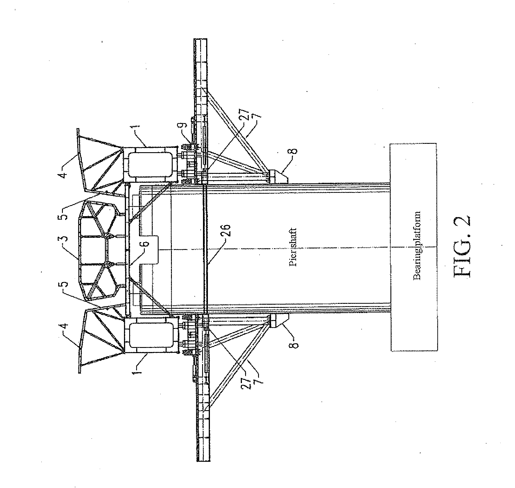
[0035]As shown in FIG. 1 and FIG. 2, the present invention includes left and right landing legs 7, left and right vertical and horizontal transfer mechanisms 9, a bearing device, and a formwork system. Left and right brackets 8 are embedded at two sides of a pier shaft. The embedded brackets 8 are installed during the construction of the pier shaft, the left and right landing legs 7 are fixedly connected to the left and right brackets 8, the landing legs 7 at two sides of the same pier shaft are fixed on the pier shaft by pulling diagonally with a finish rolled threaded steel bars B 26 and an anchorage gear B 27, and the left and right vertical and horizontal transfer mechanisms 9 are respectively disposed on the left and right landing legs 7 and move left and right along the left and right landing legs 7 horizontally.

[0036]The bearing device includes left and right main girders 1 re...


PUM


Abstract

An upper-bearing typed movable formwork used for cast-in-situ of concrete box girder in bridge engineering, comprising left and right legs (7) which are respectively fixed on a pier, left and right longitudinal/transverse sliding mechanisms (9), bearing devices and a template system. The left and right longitudinal/transverse sliding mechanisms (9) are respectively arranged on the left and right legs (7) and can move horizontally along the left and right legs (7), the bearing devices are respectively fixed on the left and right longitudinal/transverse sliding mechanisms (9), the template system comprises a bottom formwork (6), an internal formwork (3), a left formwork and a right formwork, the bottom formwork (6) is formed by screw connection of a left bottom formwork and a right bottom formwork (6a,6b) which are symmetrical about the axis line of the concrete box girder, two ends of the bottom formwork are respectively fixed on two opposite internal side surfaces of the left main beam and the right main beam (1). The movable formwork also comprises a plurality of adjustable supporting rods (14) used for supporting the template system.

Description

TECHNICAL FIELD[0001]The present invention relates to technologies of constructing a superstructure box girder in bridge engineering, and more particularly to an upper-bearing typed movable formwork used for cast-in-situ of concrete box girder.BACKGROUND OF THE INVENTION[0002]An upper-bearing typed movable formwork is construction equipment for bridge superstructure construction, and especially applicable to production of a concrete simple box girder or continuous box girder. According to different relative positions of an upper-bearing typed movable formwork main girder and the concrete box girder, the upper-bearing typed movable formwork is classified into a deck type and a through type, in which the main girder of the through upper-bearing typed movable formwork is located above the concrete box girder, and the main girder of the upper-bearing typed movable formwork is located below the concrete box girder. Compared with the through upper-bearing typed movable formwork, the upper...

Claims


Application Information

Patent Timeline
IPC IPC(8): E04G11/50
CPCE01D21/00
Inventor QIN, SHUNQUANMA, TAOYAO, SENZHU, BINGUO, RONGCHUN
Owner CHINA RAILWAY MAJOR BRIDGE ENG GRP CO LTD
Why Eureka
Try Eureka