Offshore platform for drilling after or production of hydrocarbons

a technology for offshore platforms and hydrocarbons, which is applied in the direction of floating buildings, marine vessel transportation, artificial islands, etc., can solve the problems of high cost, complicated transfer from risers, and large force and movement of vessels, so as to reduce the force of rolling or pitching movement, large storage capacity, and large dead weight measurement

Inactive Publication Date: 2005-09-20
SEMBCORP MARINE INTEGRATED YARD PTE LTD
View PDF16 Cites 47 Cited by
  • Summary
  • Abstract
  • Description
  • Claims
  • Application Information

AI Technical Summary

Benefits of technology

[0013]In addition to the pressure variations in the water under a wave it is also particle movements. The water particles move in an elliptical movement which give both accelerations and speed which varies over a wave period. The cut-out and the annular section of the cylindrical body underneath the cut-out will disturb the particle stream in the wave. The edges above and below the cut-out will create large whirls in the water which runs by. The energy which is needed to create the whirls, represents forces which act on the construction. A similar effect arises at the sharp edge between the bottom of the cylinder body and its vertical side. In addition will the annular shaped body underneath the cut-out give a certain flow resistance. The collected forces from the creation of the whirls and the flow resistance will give forces which have a vertical component which act in the opposite direction to the buoyancy forces from the wave swell. Tests have shown that by an appropriate design of the cut-out or the cut-outs and the annular body thereof, the forces which give rolling or pitching movement will be greatly reduced.
[0014]In addition to the above-mentioned favourable effect will this platform design bring a lot of other advantages.
[0015]Thus a cylindrical platform will have large dead weight measurement with regards to production or drilling equipment and large storage capacity for oil, fuel etc. The platform will be independent with regards to the direction of environmental forces and it can be anchored with a simple, fixed anchoring system. Further the risers can be connected directly to a receiving system on the platform without the need for swivel transfer or similar.
[0016]The platform can be built at a normally equipped shipyard and can be constructed and built in principle as a ship. In addition it will be possible to efficiently isolate the different main units on the platform form each other. The lower section of the platform will mainly consist of tanks for oil, ballast, fuel, possible drilling liquid etc. On the upper deck of the platform there will be necessary installations, such as living quarters, machinery and power supply, process equipment and possibly drilling equipment, to be arranged in separated areas. The circular (polygon) form of the cylinder body will give short distances between different types of equipment. This will reduce the length and the extent of pipe and cable systems and will contribute to give a cost effective platform.
[0017]The design of the platform gives the opportunity to build in a high degree of safety with regards to accidents, such as collisions or explosions. The platform will be built with double sidewalls and double bottom (ballast tanks) as in a ship. This will give high degree of safety at any accidents and reduces the danger for serious consequences.

Problems solved by technology

Disadvantages with units of this type are dependency to direction of environmental forces like wind, current and waves.
When environmental forces act across a vessel the forces and the movement of the vessel often become large.
For production on vessels this leads to high costs and it complicates transfer from risers which runs from the seabed (due to requirements to the swivel transfer etc).
Disadvantages with a known solution of this type is small dead weight measurement on deck and little storage capacity for oil, fuel etc.

Method used


Image

  • Offshore platform for drilling after or production of hydrocarbons
  • Offshore platform for drilling after or production of hydrocarbons
  • Offshore platform for drilling after or production of hydrocarbons

Examples


Embodiment Construction

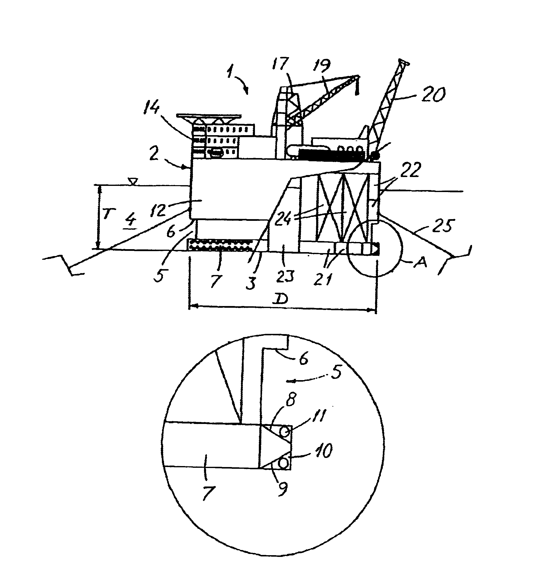
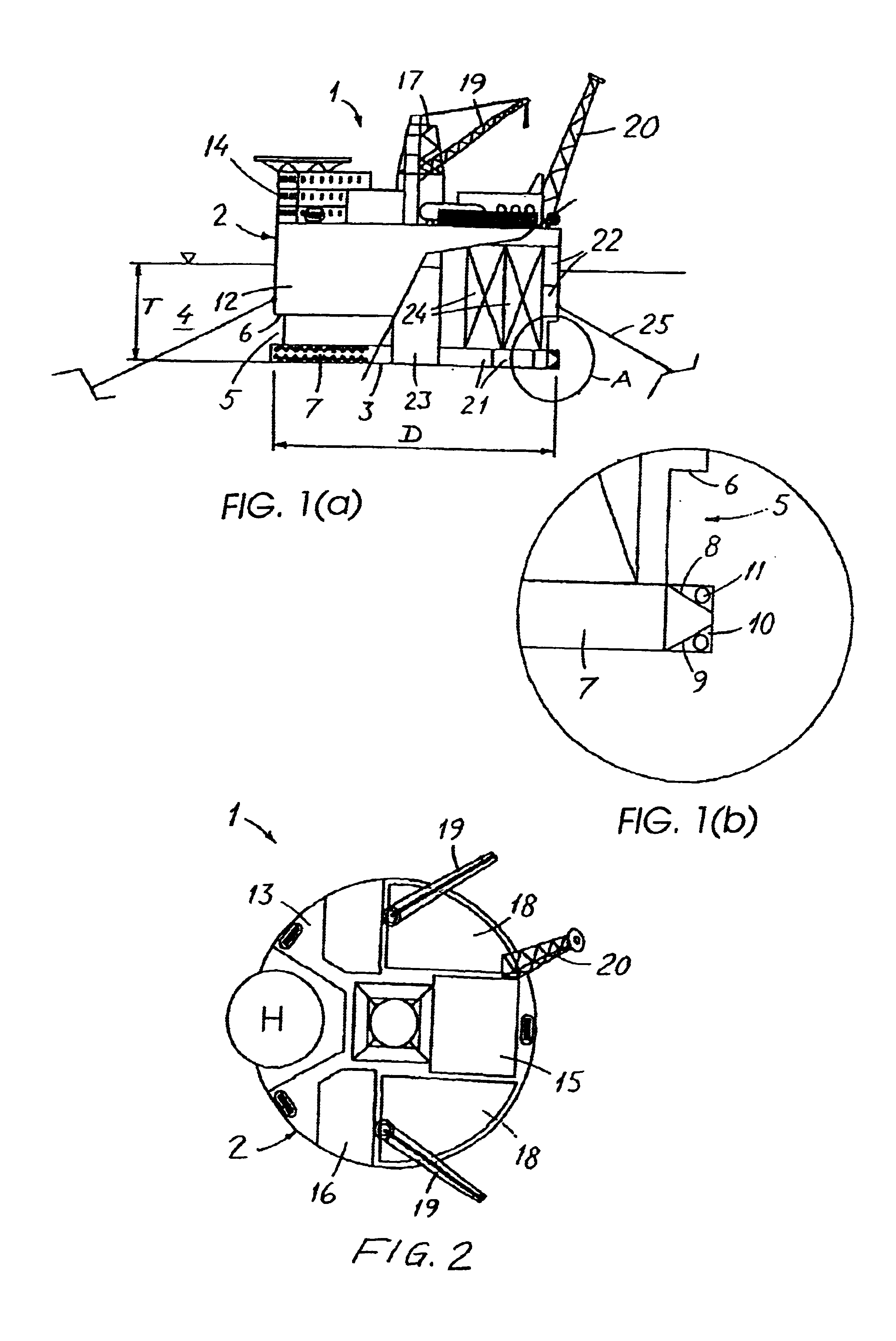
[0027]FIGS. 1(a) and 2 show a platform 1 consisting of a semi-submersible platform body or hull 2 which is designed as a vertical cylinder with a flat bottom 3. The platform is floating in the water 4. The lower half of the cylinder is supplied with a peripheral groove or cut-out 5 which runs along the whole circumference of the cylinder. In the shown design the cut-out 5 is at its upper edge limited by and large a horizontal sidewall 6, while it by its lower edge is limited by an annular body 7 which is designed with the view of achieving an extra dampening effect on the movement of the platform.

[0028]As shown in the enlarged detail A of FIG. 1(a), shown as FIG. 1(b), the annular body 7 has outwards converging upper and underside which can be formed by, annular plates 8 and 9 which is fixed at the lower end of the cylinder body 2. At the outer edge of the plates 8, 9 it is fixed by and large a vertical annular perforated plate 10 with a large number of wholes 11. The plates 8, 9 fo...


PUM


Abstract

Platform for drilling after or production of hydrocarbons at sea, consisting of a semi-submersible platform body which supports drilling and/or production equipment on its upper surface. The platform body is designed as a vertical mainly flat bottomed cylinder which is provided with at least one peripheral circular cut-out in the lower section of the cylinder since the centre of buoyancy for the submerged section of the platform is positioned lower than the centre of gravity of the platform.

Description

BACKGROUND OF THE INVENTION[0001]The present invention relates to a platform for drilling after or production of hydrocarbons at sea, consisting of a semi-submergible platform which supports drilling and / or production equipment on its upper surface.[0002]Drilling after or production of hydrocarbons (oil and gas) by use of floating units is to date dominated by two different types of units, namely vessel or semi-submersible platform.[0003]Units which are based on vessels are recognised by large dead weight measurement with regards to production or drilling equipment, and large storing capacity for oil, fuel etc. Disadvantages with units of this type are dependency to direction of environmental forces like wind, current and waves. When environmental forces act across a vessel the forces and the movement of the vessel often become large. To reduce the forces and the movement of an anchored vessel a turret (rotational body) is often used for the vessel to turn about. For production on v...

Claims


Application Information

Patent Timeline
Patent Type & Authority Patents(United States)
IPC IPC(8): B63B39/00B63B1/00B63B39/10B63B35/44B63B1/04
CPCB63B1/042B63B35/4413B63B39/00B63B39/10B63B2001/044B63B2039/067B63B2039/105B63B1/041B63B35/44
Inventor SMEDAL, ARNESYVERTSEN, K.ANG.RE
Owner SEMBCORP MARINE INTEGRATED YARD PTE LTD
Why Eureka
Try Eureka